Replacing FDD Belt on Panasonic FS-A1F (MSX2)
Almost two years ago, I acquired my first MSX computer: a Panasonic FS-A1F. I received the unit in great shape, well cleaned and maintained, and have enjoyed many hours of gaming and testing out different sound sources the MSX can access. The Floppy Disk Driver, however, had a busted belt that needed to be replaced, limiting me to cartridge programs.
As for many disk drives of the 1980s, the original belts deteriorate over time, either crumbling away or metamorphosing into a sticky, black goo. Although I have replaced similar belts on my Famicom Disk System and several Roland and Akai samplers, this one proved a different kind of job. According to the MSX community, de-soldering wire is required to maneuver the new belt onto the spindle; any attempts to remove the screw holding the optical sensor in place risk permanently damaging the alignment, leaving the FDD unusable. Although a few guidelines and diagrams for safe replacement of the belt exist, I have not been able to find a detailed, step-by-step guide, at least not in English, so I’m sharing my process here with many photos. I hope it will be helpful to others.
Items needed:
Soldering iron and solder
isopropyl alcohol and cotton swabs
static-free tweezers
#1 (long narrow shaft) and #2 Philips head screw drivers
Miniature jeweler’s flathead screwdriver
I used a belt purchased from Console5 and have had good experiences with other belts from that merchant for my FDS and various samplers.
Part 1: MSX Disassembly
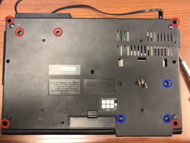
Begin by removing the screws on the corners and the screws holding the rear cartridge slot and the FDD drive. NOTE: the three screws holding the FDD are different than the others and have washers.
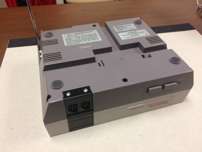
Once the screws are removed, flip the unit over and slowly start separating the top cover, beginning with a corner and gradually making your way around. BE VERY CAREFUL when pressing on the release tabs, especially around the FDD, as they can break easily.
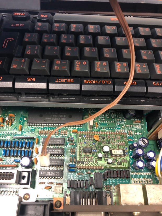
While slowly removing the top cover, unplug the wire connecting the cover to the main board.
Now that the lid is completely off, locate and remove the two screws holding the keyboard into place.
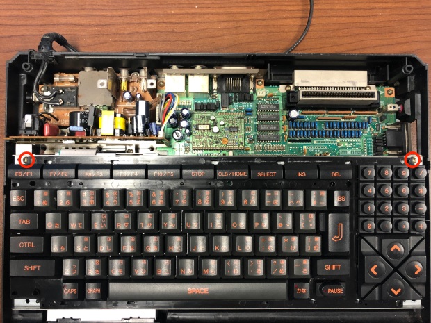
While the keyboard can be completely removed, rotating it over toward the right, while propped on another object, will allow you to keep the ribbon pins connected, as they are fragile.
Part 2: FDD Removal and Disassembly
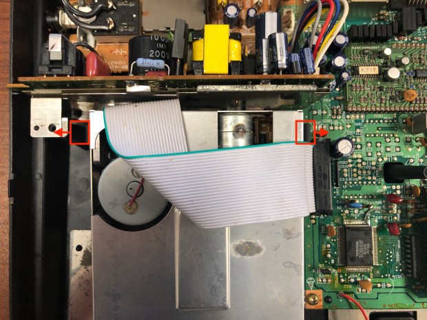
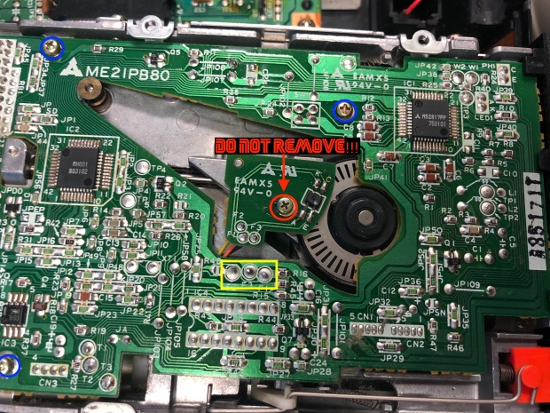
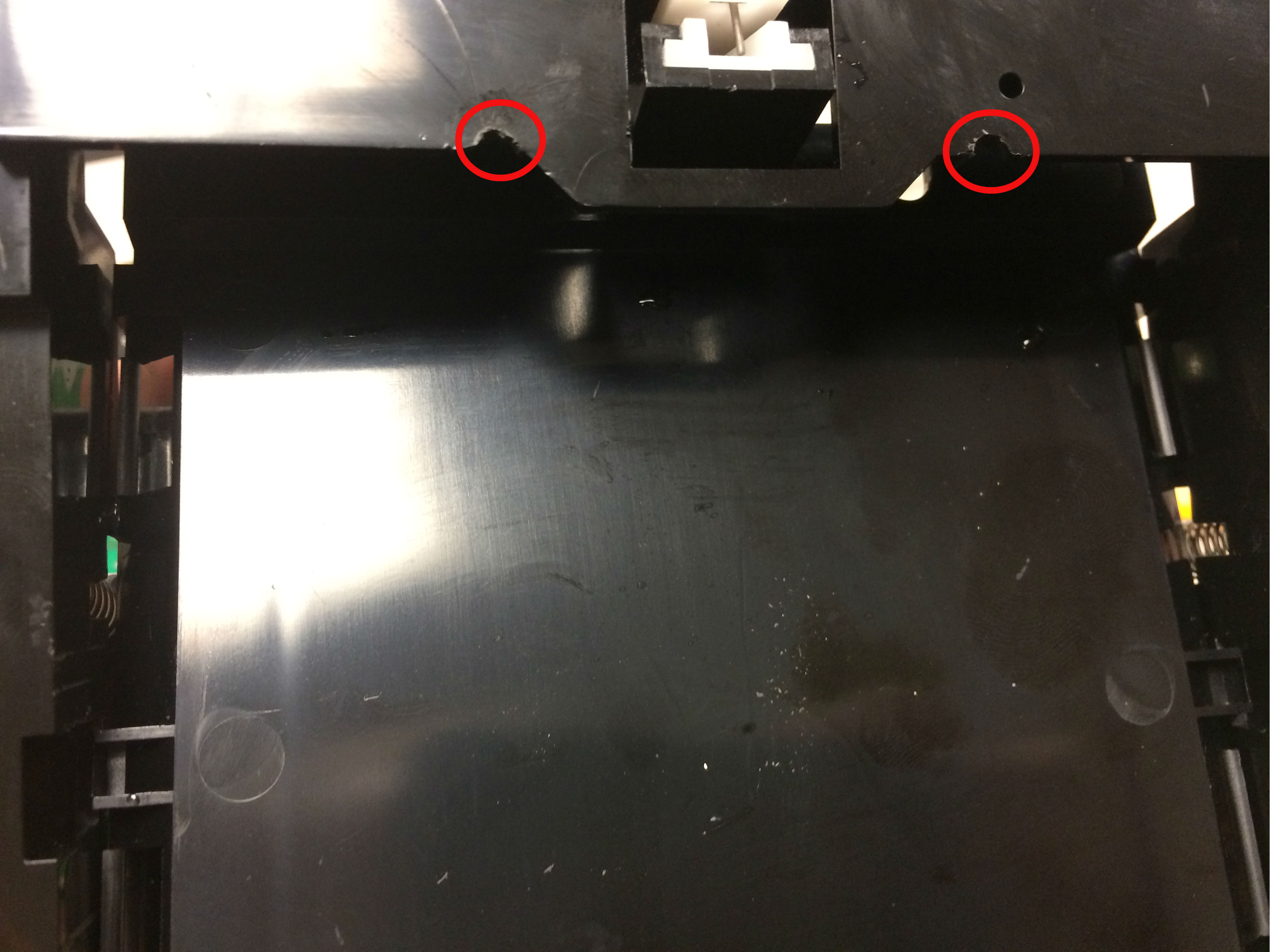
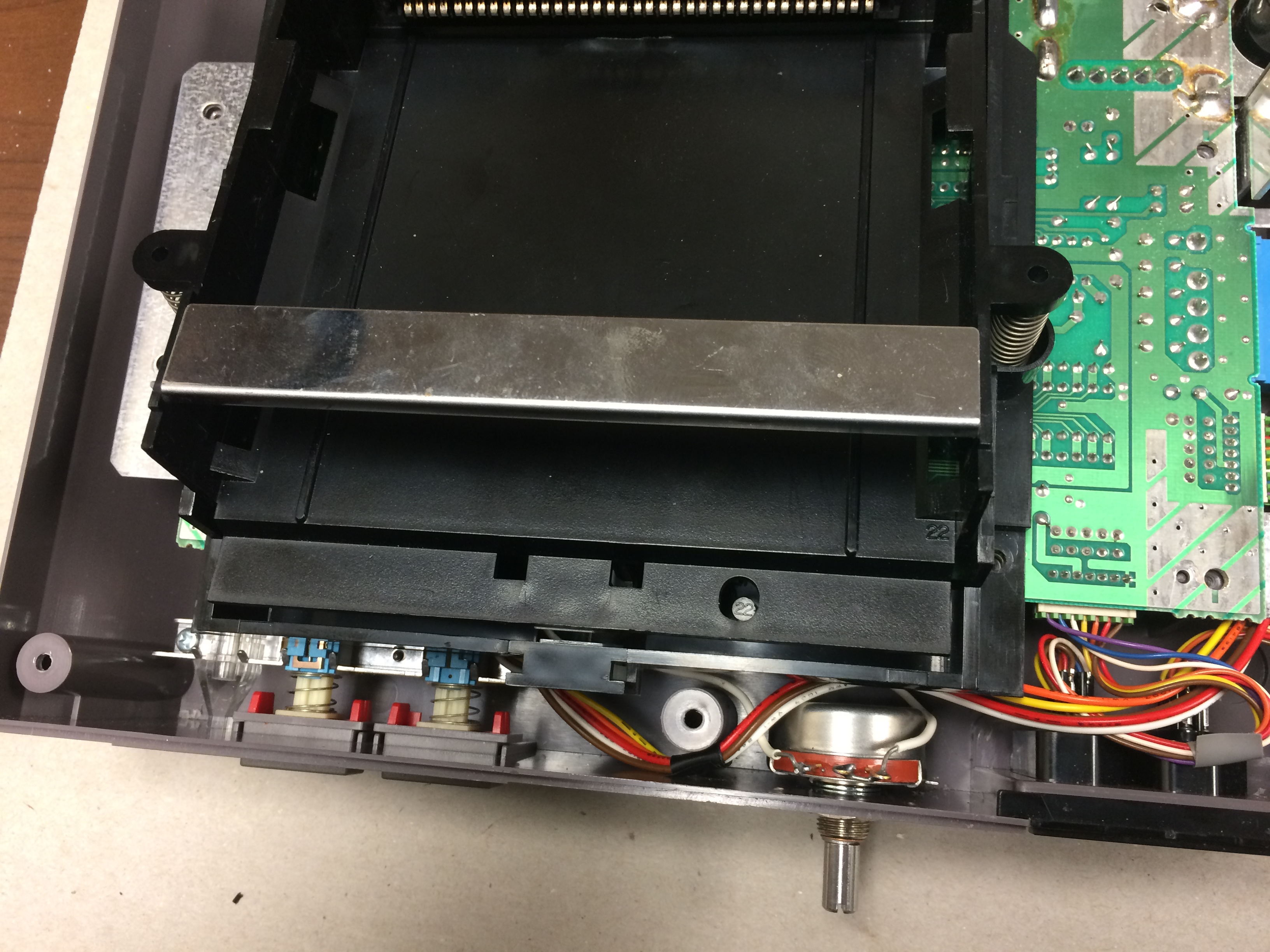
Make sure the three small screws holding the FDD in place from the bottom case (above in blue) have been removed. Next pull the black tabs to the sides to allow the FDD to slide out.
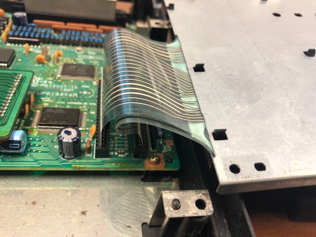
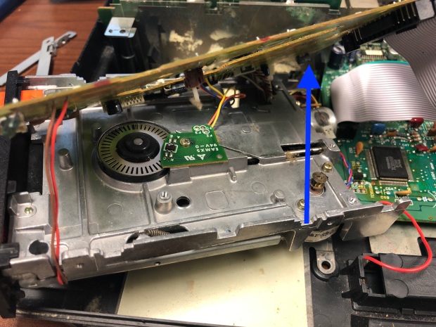
It is possible to keep the ribbon cable connected while continuing with this belt replacement; however, to get clear access to the belt drive and spindle, you’ll need to get under the metal plate on the top of the drive. Begin by flipping the drive over and removing the four screws that hold up to two mounting plates on the sides.
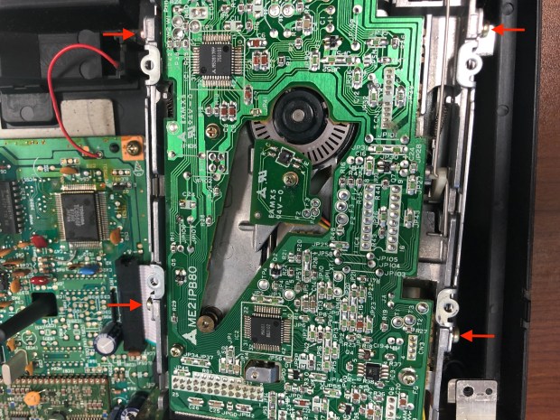
You’ll then be able to start pulling the metal plating off, first by unhooking the tabs from behind the drive’s front cover.
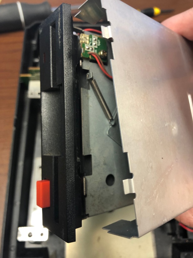
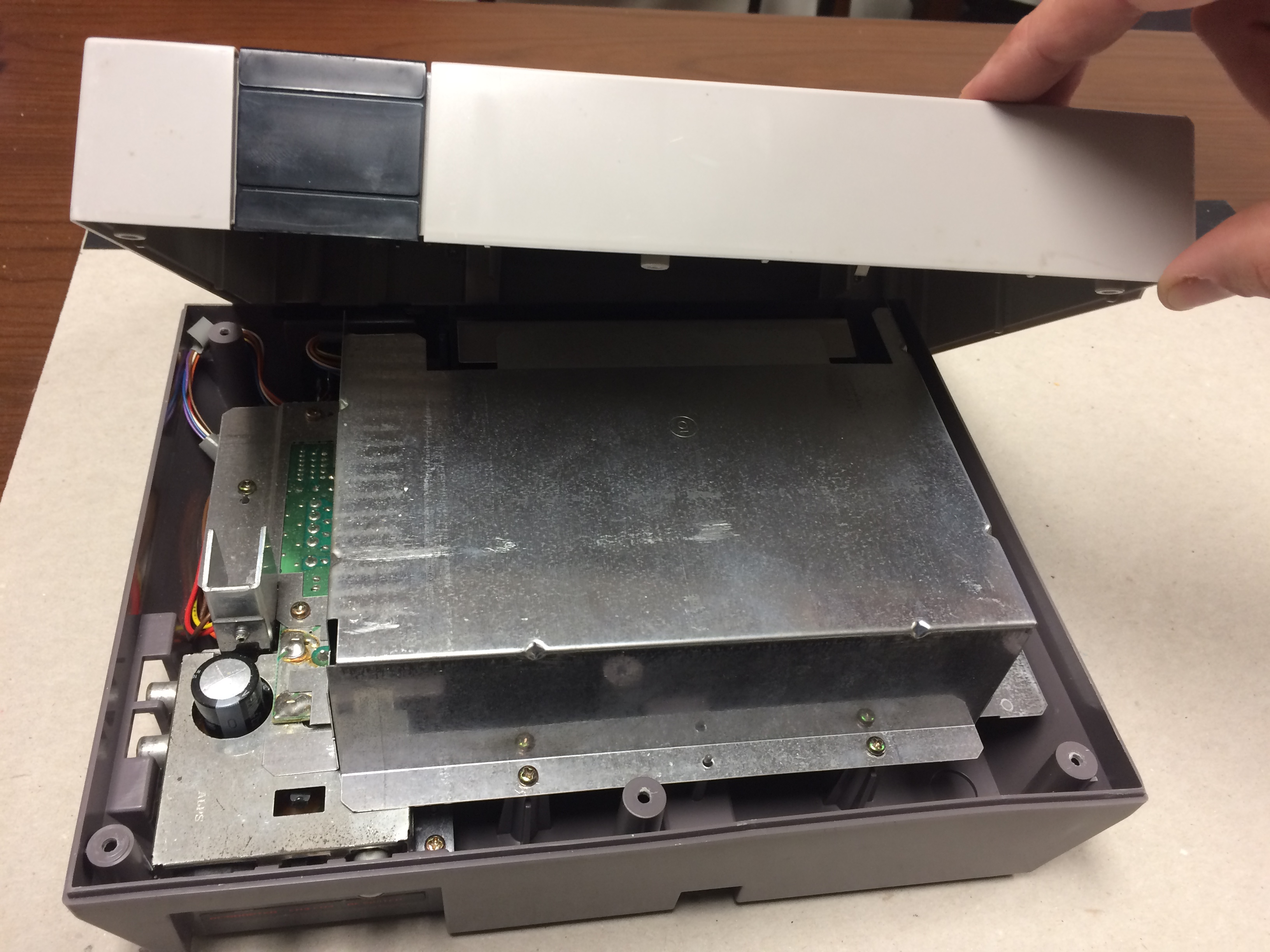
You’ll then need to get under the PCB, so remove the three screws holding it down, but DO NOT remove the screw that’s holding the optical sensor in place. You’ll see the three solder joints that will be undone later to allow the new belt access to the spindle.
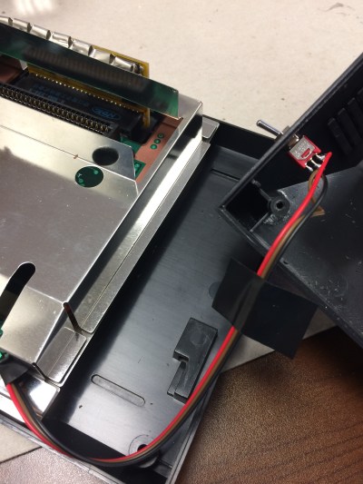
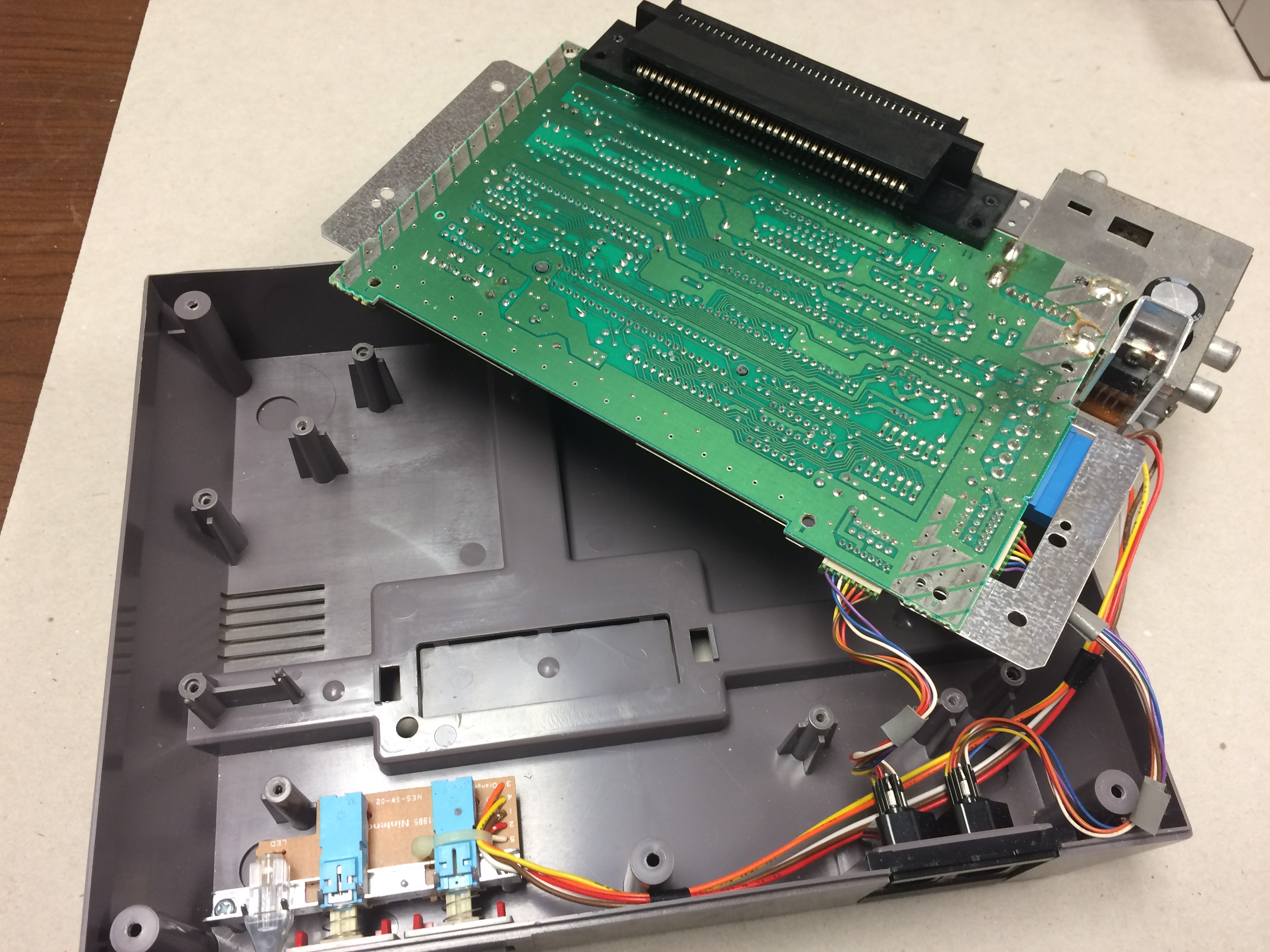
With the top metal plating removed, you’ll be able to access and unplug the red and blue wires connected to the PCB.
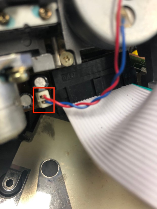
Removing the screws and the red and blue wires will provide enough give that you can lift the PCB board up on one side in order to install the new belt.
Part III: Cleaning and Installation
Chances are the original belt has deteriorated to the point that it has broken off in several places and left a heavy amount of black, sticky residue on the spindle and pulley. You’ll need to do a thorough job removing the broken pieces with anti-static tweezers and cleaning with isopropyl alcohol and cotton swabs. Some stubborn spots may require you to scrape the residue away with a small jeweler’s flathead screwdriver.


I’ll stress here that it is essential that you do a thorough job cleaning the tracks on the spindle and pulley. Make sure to check under the pulley’s top lip for small traces of black goo that are hiding there. The tracks should be slippery clean or the new belt will have problems staying on track. Don’t be surprised if you have to use several cotton swabs to get the job done.


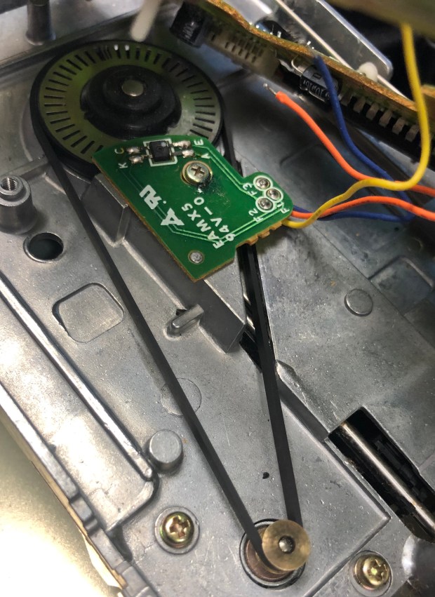
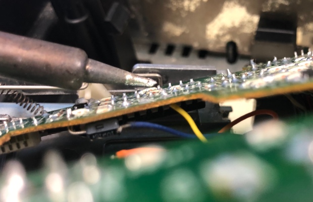
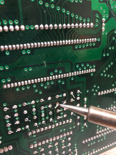
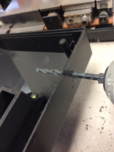
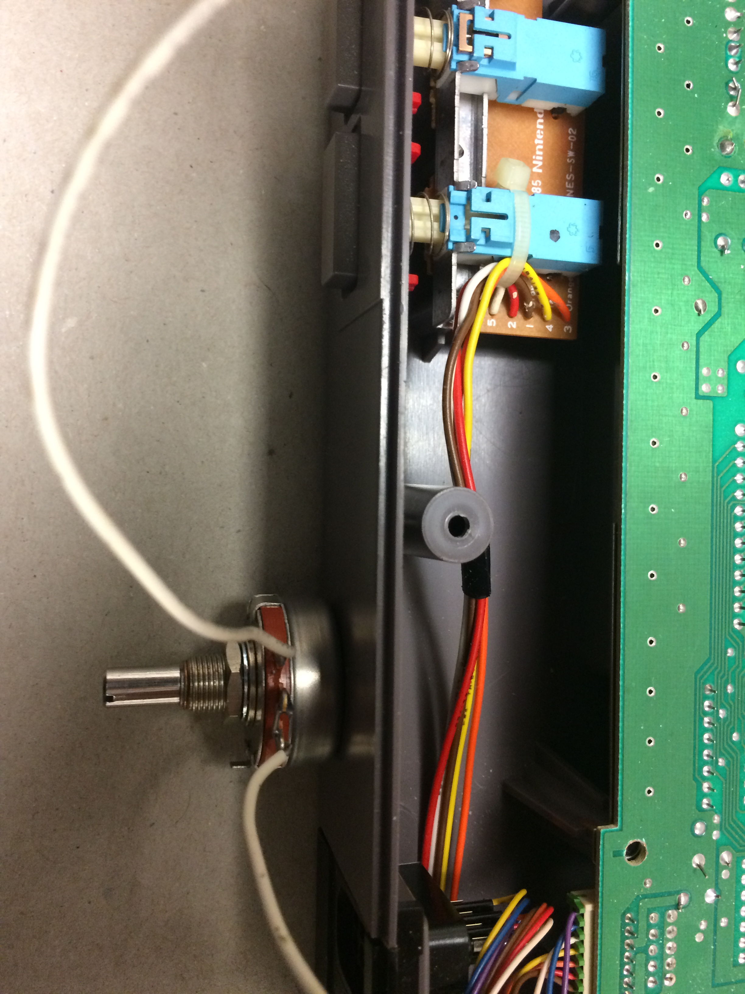
Before installing the new belt, you’ll need to desolder the orange, blue, and yellow wires at pads F1, F2, and F3. The wires run through holes on the PCB, so you can simply warm and melt the solder pad on the top of the PCB and pull the wires out from the bottom of the PCB with the anti-static tweezers. Remember to mark down which color wire goes to which pad.


Then hold the three wires together with your tweezers, so you can circle the belt around the wires from the top. Pull one side of the belt over the optical sensor board and slide the other side of the belt just under the corner of the optical sensor board so you can stretch the belt onto the spindle and pulley.


Use your finger to turn the spindle several complete rotations to ensure that the belt is not getting stuck or riding up on the track. The belt should be tight, but not difficult to turn smoothly.
Part IV: Reassembly
You can then start putting the drive back together, first by soldering the orange, yellow, and blue wires back to F1, F2, and F3 by flowing pads from the top of the PCB and sliding wire through the hole from the bottom with anti-static tweezers. You may need to apply additional fresh solder to the pads on the top of the board after the wires are fed through to ensure joint strength.
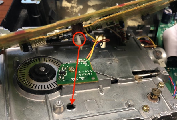
With the wires re-soldered, reverse the previous steps by plugging in the red and blue wires and screwing the PCB back in place. Be careful to feed the narrow white pin beneath the PCB through the hole on the tray below before putting the screws back on.
Then, return the metal top plating and side mounting panels and drop the drive back into place between the two black tabs.
Flip the keyboard back over, put the screws back in, and plug the beige wires back in so you can place the unit’s outer shell back on. Finish by screwing in the outer case from the corners and securing the screws back under the FDD and rear cartridge slot.
The entire procedure took me about an hour to complete. Take photos so you can remember how things should look when you put the unit back together; maybe they’ll come in handy if you find a more efficient way that you’d like to share!
If you have any questions or suggestions for a different method, please share in the comments. Thanks for reading!
Sources:
Sega Master System FM Mod
About 60 Sega Master System games include music data for Frequency Modulation (FM) synthesis. Yamaha’s YM2413 (or OPLL) sound chip, employing only 2 operators, was a cheap alternative to the FM synth chips found in its flagship DX7 keyboards and frequently employed in advanced arcade cabinets. Sega’s Mark III console, released only in Japan, could play the FM data when an external sound unit accessory was connected, and, later, the Japanese version of the Master System included the YM2413 chip in the internal circuitry. Unfortunately, the North American and European releases of the Sega Master System were not built to support the expanded audio, even though most game cartridges retained the FM sound data.
I recently modded two North American Sega Master System consoles to read and perform the FM sound data, using a PCB with the YM2413 chip that was built and designed by Tim Worthington. These mod and kits are explained on this website. Although diagrams and schematics are posted online, I have not found a detailed, step-by-step guide; therefore, I am blogging my experience with installing two kits for those, like me, who may need more guidance. I am not an electrical engineer by any means, so please comment below if you have any suggestions for improvement. My approach worked well for my two consoles, but please be aware that differences exist in the variant releases of the Sega Master System.
EDT’s video proved an invaluable resource to my approach.
SUPPLIES (Required)
-Tim Worthington’s FM Sound Kit (available for purchase here).

-Phillips head screwdriver
-Soldering iron
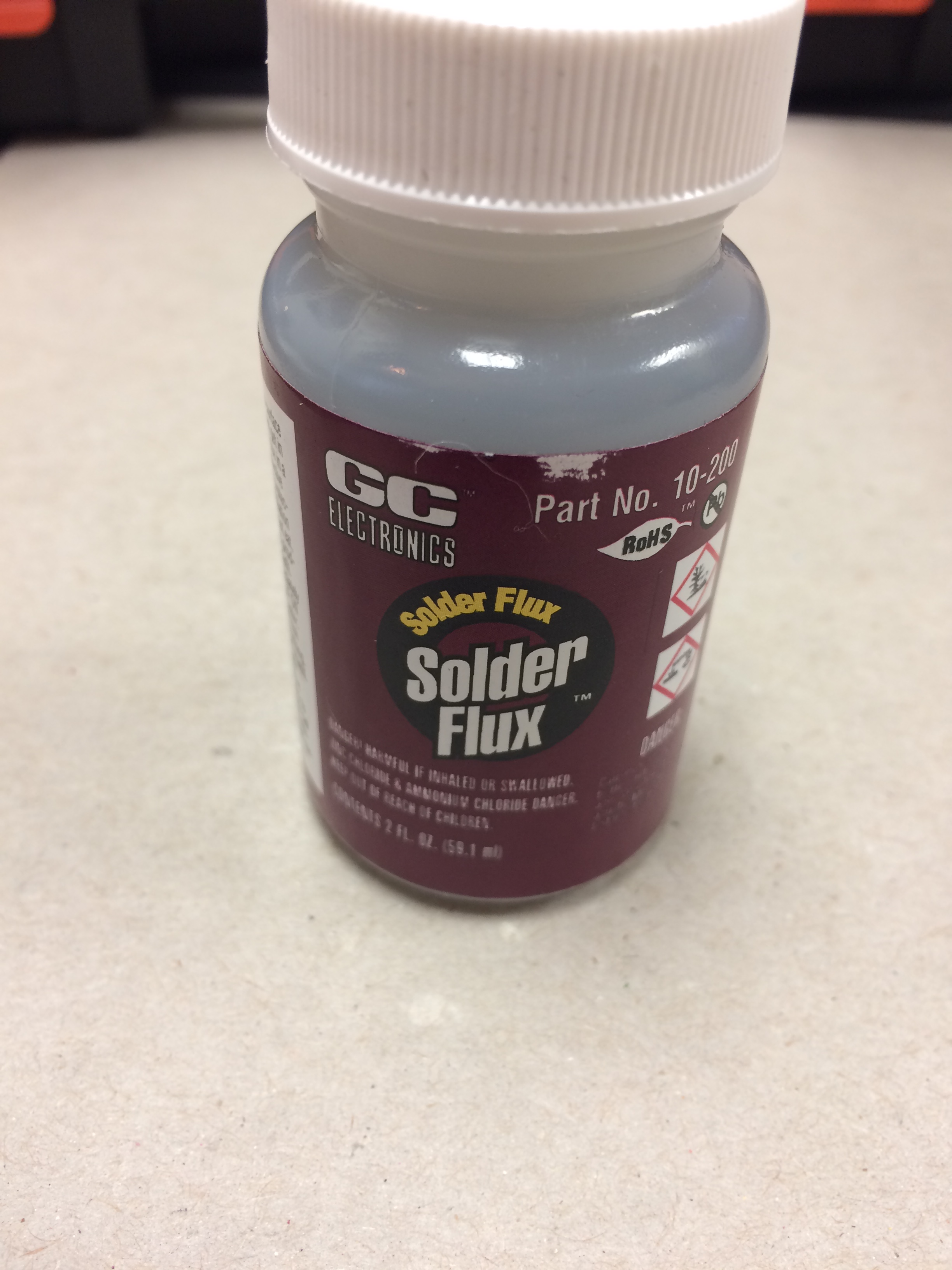
-Solder and flux
-Drill with 5/16 bit
-Small gauge wire cutters
SUPPLIES (recommended)
-Electrical tape
-Desoldering pump or wick
-Shears/Tin snips
-Jeweler’s flathead screwdriver
-91% Isopropyl Alcohol
-Cotton swabs
PART 1: Preparing the PCB
-Slide the pin connector through the holes in the PCB and solder each pin on the rear side. To ensure perpendicular alignment, use something to prop up the board so the two rows of pins are even. Careful not to bridge adjacent pins (see picture); use a desoldering pump or wick to remove any excess solder.

-Slide in the toggle pin connector so that the long end runs parallel to the front of the PCB. Then solder the 3 short end pins on the rear of the board (where the text FM and Japan FM is printed.

-You’ll see that the plug on the provided wire for the toggle switch will slide right onto the 3 pins that are running parallel to the front of the PCB.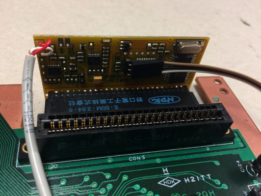
Part 2: Preparing the Toggle Switch
-While the plugs on the wire provided with the kit fit snuggly on the pins for the PCB, I found that they were too small for the terminals on the toggle switch.
-Therefore, I cut off the plug on one end, stripped the 3 wires, and then threaded through and soldered to the 3 terminals, being careful not to bridge any of the three wires with solder on the back of the toggle switch.

-Note: Keep the plug on the other side of the wire, as it will slide easily onto the PCB pins.
Part 3: Preparing the SMS Console
Disassembly. This video may be helpful.
-Remove the six screws on the rear of the console case with the Phillips screwdriver and pull apart. Put screws and console top aside.
-Then remove the 5 screws around the base of the RF shield as well as the screw on top of the RF shield. NOTE: the screw on top of the RF shield is different and includes a washer.
-Finally, remove 7 additional screws that hold the motherboard in place. See the diagram pictured below (one of the two screws on the bottom left is slightly cut out of the photo).

-You can now remove the motherboard.
Wiring SMS motherboard
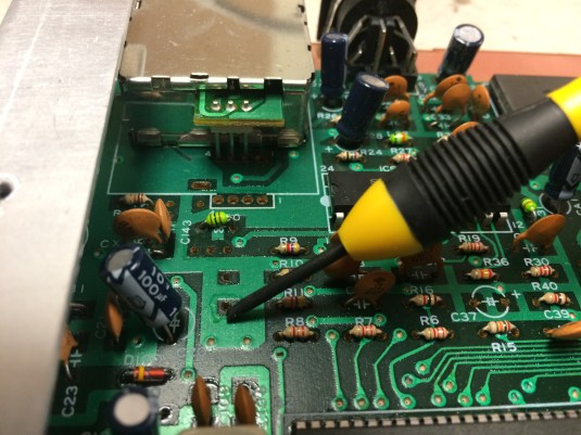
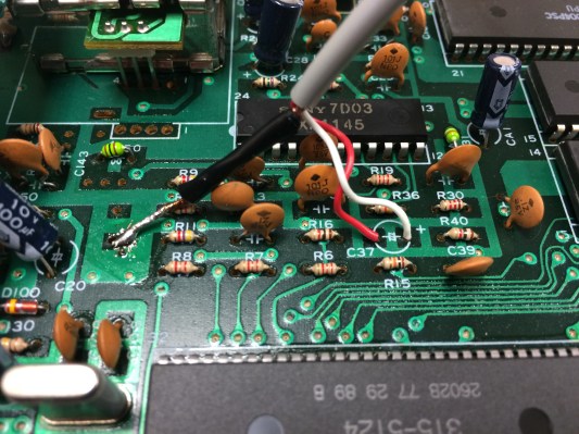
-Remove the electrolytic capacitor at C37 by locating the traces on the rear, warming the existing solder with you iron, and pulling the capacitor away from the other side when the solder is molten.

-Locate ground plane to the left of the same capacitor field and scratch away the green coating with a jeweler’s flathead screwdriver.
-Prepare the wire provided by stripping the sleeves to reach the target locations on the motherboard and then tin the ends.

-Thread the red and white wires though the positive (+) and negative (-) polarities at C37, and solder the traces on the rear of the motherboard. NOTE: The image provided on the website above has the red and white wire locations reversed. The white wire should be on the right (+ve), and the red wire on the left (-ve).
-Apply flux to the ground plane you just scraped on the component side and solder the threaded copper wire to it. Once completed, wrap electrical tape around exposed wire threads to keep them from reacting to nearby components.
Part 4. Final assembly.
-Clean the pins on the expansion port with some alcohol and cotton swabs.
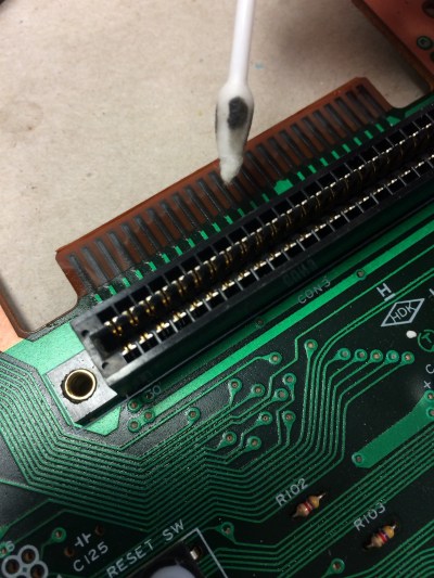
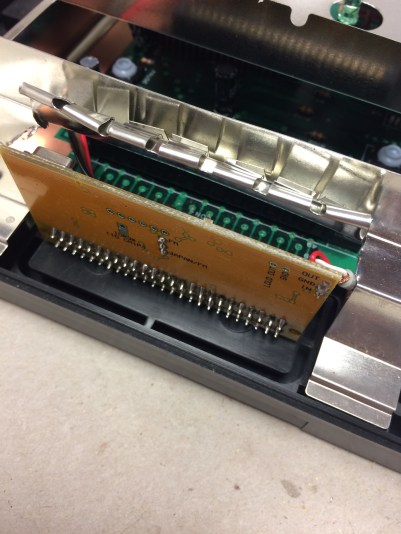
-Slide the pin connector on the PCB onto the expansion port pins. It should slide all the way in tightly.

-Attach the motherboard to the bottom casing with the 7 screws left to the side.
-Use shears or tin snips to cut the RF shield and roll the fingers up so the FM sound board will clear without making contact with the shield.

-Attach the plug on the toggle switch wire to the PCB (if you haven’t already) and put the RF shield back into place with the 5 screws left aside, as well as the smaller one for the top of the shield that has a washer.
-Use a 5/16 bit and drill a small hole through the lid of the console in the desired location. I used the rear left side, so it would have the same clearance as the power and AV cables wherever I set up my SMS.
-Make sure the hole is just wide enough to slide the threaded part of the toggle switch through and fasten with the included washer and nut. Electrical tape can be used to hold the wire in place, so it will not block access to the cartridge and card slots.
-Carefully place the console lid into position, making sure that the toggle switch wire doesn’t get pinched. (Note: I took photos during both console mods, so pay no attention that the toggle switch wire colors are different at times).
-Put the 6 outer casing screws back in. Done!
Optional. Label the toggle switch. The direction will depend on how the wires were connected to the pins with the plug on the PCB.

Once assembled, you should be able to boot the FM sound data from the Sega Master System cartridges that have it (they are listed at the website above). Some games will require you to use the Japan FM setting on the toggle switch. Other games will require a patch or ROM from a flash cart like the Master Everdrive. You cannot toggle during gameplay, as the FM data is only loaded at boot up.
Many thanks to Tim Worthington for an outstanding mod and kit!!!
Please leave comments below if you have any questions or any suggestions for improvement. I hope this step-by-step guide will be helpful! =)
NES Expanded Audio: 100k Pot Mod
Like many others, I modified my original NES with a 47k resistor to support expanded audio playback. While connecting expansion pins 3 and 9 does access the additional channels, the balance is very inconsistent. This is due to variability in the chips added to Famicom cartridges and to the Famicom Disk System and how they were mixed with the primary sound created in the console. Each expansion included both the additional audio data and the instructions for how it should be mixed with a Famicom. A fixed resistor therefore results in a fixed mix with the console.
A potentiometer, used to vary the ratio of voltage divided between two circuits, can be wired as a variable resistor (i.e. rheostat) to provide dynamic control of the extra channels. Instead of connecting all three pins, you just wire one of the outer terminal pins and the middle pin (wiper). I found this image helpful in demonstrating the difference. You could choose to bridge the extra terminal pin to complete the circuit in case the wiper should fail over time.
Since there were no visual guides specifically for a 100k pot mod to the NES, I decided to post my experience. I’m no expert, so I’m grateful for the post by Wesley Almond that guided me along the way. Also, thanks to Brad Smith (a.k.a. rainwarrior) for the 100k pot mod idea.
MATERIALS USED:
A)-regular philips head screwdriver
B)-jeweler’s flathead screwdriver

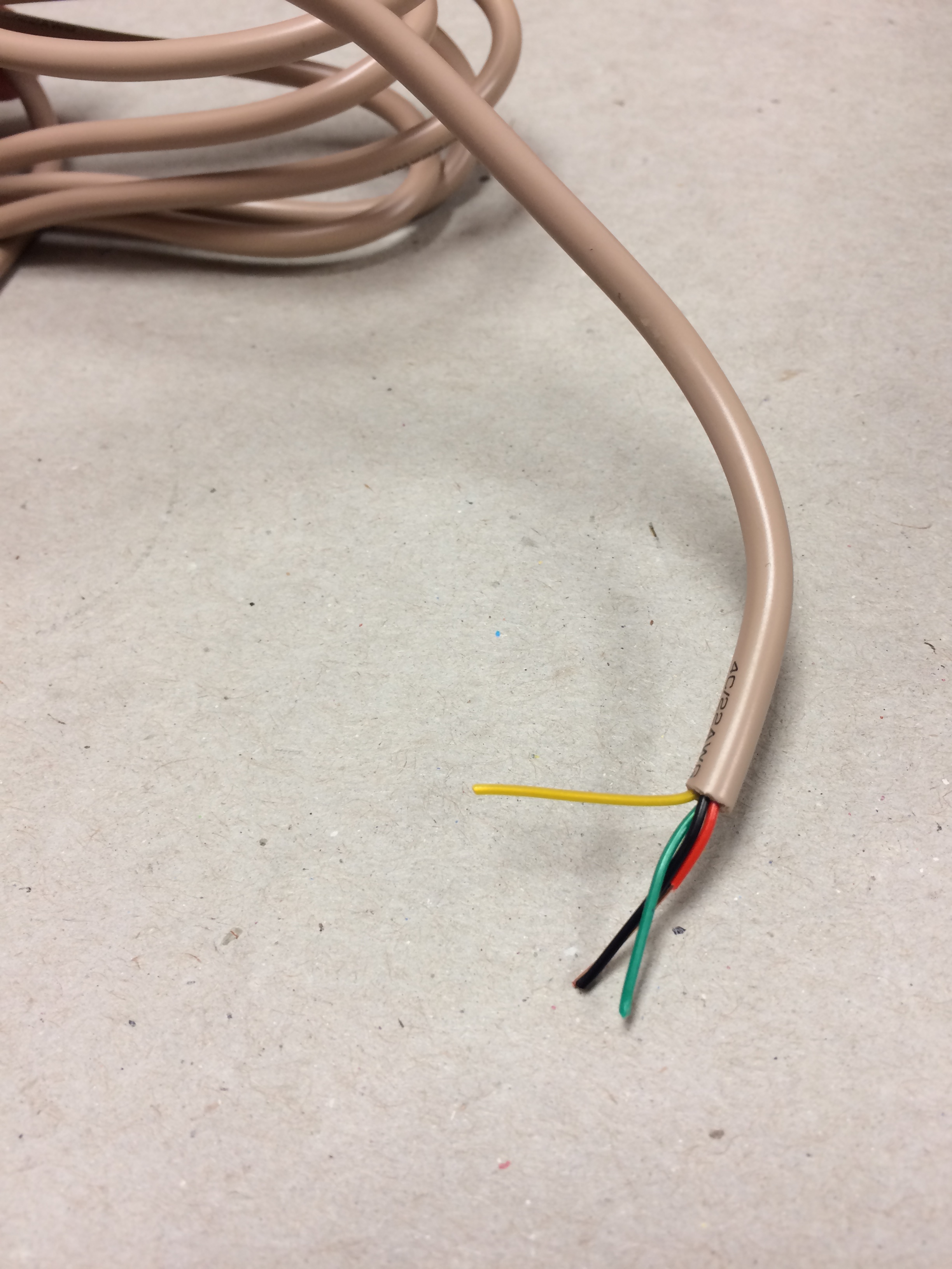
C)-coated, solid wire w/ small gauge. TIP: Have your local electronics shop sell you a few feet of 22 AWG/4 conductor security wire for practically nothing, strip, and choose among FOUR COLORS!
D)-wire stripping pliers (for small gauge)

E)-soldering iron and solder

F)-flux: to prevent oxidization at soldering joints
G)-drill with 3/8 bit
H)-100k Potentiometer. TIP: Some come with “off switch” that is engaged with a click when turned all the way, counter-clockwise.

STEPS TAKEN
1-Remove the 6 outer casing screws with the philips head screwdriver.
(NOTE: All of the screws removed in this mod are the same, except for 2 slightly longer ones later in the process. I still recommend keeping them grouped and on a surface where they won’t roll away!)

2. Remove the bottom casing to reveal the heat shield.
3. Remove the 7 screws on the heat shield + the screws over the RCA and RF jacks.

4. Lift the shield slowly to navigate around any obstacles

5. Remove the 6 screws from the cartridge tray. Note that the inner screws of the bottom pairs (blue) are slightly longer than the other screws.

6. Pull the cartridge tray out and then lift up.

7. Slowly pull the board out and flip over gently around the course of wires.

8. Locate the Nintendo lockout chip and pry off the 4th pin from the left—I used a jeweler’s flathead screwdriver to pop off and bend back.


9. Slowly flip the board back over and set back into the console casing.
10. Prepare Pot: At this time, warm up and tin your soldering iron. Cut a pair of 5-6 inch wires and strip the coating back on both ends. Warm wires with soldering iron, dip in flux, then warm solder with iron and connect one wire to the middle terminal on the pot, which controls the wiper, and the other to the right terminal on the pot. I shaped my wire like a hook and looped in the pot rings before applying solder.

11. Once the pot has cooled, set it outside the console between the reset button and the controller jacks. Mark your drilling location on the plastic casing where the pot knob will go, leaving enough clearance above the pot to reassemble the console.
12. Drill a small pilot hole and then use a 3/8 drill bit to create an opening for the threaded pot knob. Careful not to drill into the wiring, which can be pulled back slightly and even held out of the way with electrical tape if needed.

13. Apply some side pressure (or use a dremel) to widen the opening as needed until the threaded knob pulls through snug, and then fasten with the nut.

14. Locate pins 3 and 9 on the board, used to channel expanded audio.

15. Solder the wire attached to pot’s middle (wiper) terminal to pin 3 and the wire attached to the pot’s right terminal to pin 9. TIP: Make sure there is enough slack for the wire to run over the board and loop along the bottom of the casing before routing back up to the pot.

15. Use side of drill bit (or dremel if you have one) to carve out two small openings along the edge of the cartridge tray where the wire will not be pinched when pushing tray down during reassembly. Alternatively, you could use longer wire and run completely around the tray and approach pins from the side.
16. When reassembling the cartridge tray, make sure to slide the wires into the openings before pushing tray down. Also, remember to use the two longer screws in the correct locations.
17. Re-attach the heat shield and the bottom casing, and flip over. DONE!

18. Test your modded NES! NOTE: This mod will not work with VRC7 (Lagrange Point) unless you are using an actual Lagrange Point cartridge, with the 60-to-72 pin adaptor wired to route the cartridge’s audio. Most other expanded audio will work via Powerpak flash cart. Use pot knob to mix expanded audio with console audio to your liking! Turn the pot knob off when not in use.
Hope this helps newbies like myself! Please comment with any questions or feedback; if there’s a better way to do this, let me know and I’ll update!
Writing Repeat, Writing Repeat, …
For the past several years, I’ve supplemented the usual, high-stake writing assignments (papers over 1000 words) with short reflection posts to the course LMS. These essays are limited to 250-300 words and I grade them on a 5-point scale. Depending on the course, I might assign anywhere between 8-12 posts. They are quick to read, easy to grade, and valuable to enhancing class discussions. Students score samples at the beginning and mid-point of the semester to calibrate themselves to the rubrics and to establish a standard for quality work.
My intention with these assignments is to cultivate regular writing (and thus thinking) habits, to prepare students for classroom participation, and to give students many opportunities to practice putting arguments forward and supporting them with class resources. With the brief post I make to the entire class that summarizes my feedback and offers suggestions for improvement, some students are able to make significant improvements in mechanics and style.
The majority of students, however, find a formula that earns them a ‘4’ on a continual basis. Part of this trend stems from the bell-curve distribution of performance and the limited point values to choose among. However, I am starting to believe that the repetitive nature of the assignment encourages students to settle into a groove (or funk?) that will predict their performance for the majority of the semester. Although the topics for the prompts change from assignment to assignment, the process of writing remains unchanged.
My recent experience in article co-authorship, collaborative peer review, blogging, and the various genres of writing one finds in the life of an academic (formal letters, public presentations, assessment reports, scholarship, and creative work) seems at odds with the repetitive writing format we often expect of our students. We train them to write in the style of our disciplines or to the “standards” based model of expository writing. If writing is not improved in repetitive writing activities of the same type, then perhaps we are not introducing students to enough variety of writing practices to give them the the perspective needed to make notable changes.
I plan to diversify the short writing assignments in the future, although I will still use a simple, 5-point rating system. In addition to posts to a discussion forum, I’m considering a class blog project, co-authored papers, and creative/fun fictional writing, among others, to stretch the students’ exposure to various styles and formats. The old adage that one improves by repeating a task over and over again is often challenged when a variety of complementary skills is lacking. This is why athletes cross train and why our students learn to think analytically, quantitatively, and critically in a diverse, core curriculum.
I’m curious what types of short writing assignments others use.
My Experience Publishing with Hybrid Pedagogy
I had the privilege to publish a short-form article with Hybrid Pedagogy this summer. It was a collaborative process through and through. The essay was co-authored with my colleague, Jessica Mahoney, and the peer-review process was completely open, allowing me to directly converse with the journal’s editors as Jessica and I made revisions.
As scholarship adapts to changes in technology and information sharing in the digital age, I see tremendous benefits in this sort of peer review. The time lags that occur in the traditional format may be suited to longer, more in depth writing, but research aimed at keeping up with the rapid exchange of ideas will need a more instantaneous platform. Although I doubt traditional scholarship will completely die out–it does offer something of tremendous value–I suspect the acceptance and quality of short form writing and open peer review will continue to grow.
Furthermore, I believe this is a great model for student writing. The systematic routine of leading students through the motions of 5-part expository essays may have little relevance for their writing in the future. Students should write to learn to think and communicate both valid and compelling ideas. Co-authorship and open peer review may be the way to increase motivation and participation.
Teach and Learn Carnaval with Nearpod
![]() Teachers have all the fun when it comes to new educational resources. Not only do we play with the latest toys at conferences, workshops, and meetings, but we get the “instructor version” with bells and whistles that students are not privy to knowing: assessment data, practice quiz questions, presentational aids, and suggested exercises. These bonuses, however, usually contain resources that could enhance learning if given over to students. Their very nature represents the contexts and layers involved in the curriculum and an open engagement with students invites self-guided learning experiences.
Teachers have all the fun when it comes to new educational resources. Not only do we play with the latest toys at conferences, workshops, and meetings, but we get the “instructor version” with bells and whistles that students are not privy to knowing: assessment data, practice quiz questions, presentational aids, and suggested exercises. These bonuses, however, usually contain resources that could enhance learning if given over to students. Their very nature represents the contexts and layers involved in the curriculum and an open engagement with students invites self-guided learning experiences.
The interactive presentational software Nearpod permits this role reversal with a recent update to its software: one mobile app that can run either student or teacher versions. While this simplification offers convenience, it is serendipitous for the pedagogue with a class-flipping slant.
Teams of students responsible for presenting Robert Schumann’s Carnaval, Op. 9 will learn more from the experience using Nearpod than PowerPoint or Keynote when they engage with the interactive slides. Some of those features provided by the Nearpod software include polls, quizzes, and drawing exercises. The important pieces of the puzzle involve an intentional and thoughtful planning stage as well as an assessment and reflection stage. Students need to take ownership of important themes and concepts from the lesson and evaluate their role in bringing their classmates to them.
Here are two examples of the drawing interactive slide from a Nearpod presentation on Carnaval:


The poll slides function very similarly to the clicker poll technology and provide immediate material for in-class discussion.

Finally, short quizzes scattered throughout presentations hold students responsible for assessment.

While these tools were originally intended for teachers to employ in lectures, the easy access for students permits them to reverse the classroom and think about the important contexts of the course beyond the required content. It’s ok to put students in the driver’s seat from time to time as long as you know when to take the keys back.
Annotating Josquin with Goodnotes
 There are several annotation apps available for iPad, including iAnnotate and Penultimate, but Goodnotes has been my favorite so far for the music classroom, particularly for score analysis. The functionality of Goodnotes across multiple platforms and the ease with which scores and annotations are imported and exported provides ample opportunities for making analysis more interactive in the flipped environment. For students and classrooms with easy access to mobile technology, Goodnotes is a low-cost solution to expanding textbook resources quickly and efficiently.
I often introduce peer analysis activities to encourage students to think beyond the isolated examples of the course anthology. Most music history textbooks, for example, include Josquin’s motet “Ave Maria…virgo serena” to illustrate the new compositional techniques of the Franco-Flemish school circa 1500 CE, namely those described by Pietro Aron in Toscanello in musica (Venice, 1523/rev. 1539). The most striking of these features include the pervasive “points of imitation,” paired voices, and homophonic textures, which reflects a sensitivity to text setting achieved by composing all voices at once (vertically) instead of in linear stages. Simulating the stages of composition and text setting with an activity facilitated by Goodnotes helps students solidify concepts from the book and anthology and reflect on the conditions for composition, performance, and dissemination.
After discussing “Ave Maria virgo serena,” teams of students are assigned a different motet by Josquin to analyze and present to the class. Goodnotes facilitates teamwork outside of class by its compatibility with a variety of applications, Dropbox, Evernote, Google Drive, to name a few. Individual students can work with a specific color to represent their contribution with the file-sharing capabilities of the external programs.


One advantage of Goodnotes is its compatibility with Safari on the iPad, which permits students to seek and acquire examples using their own judgment rather than relying of the instructor to provide. Note in the second screen shot that the Safari app provides a box for opening .PDF files from web resources directly into Goodnotes, like the International Music Score Library Project.
The Goodnotes workstation will assist student learning outside of the classroom, offering the autonomy of choosing a variety of annotation styles and of managing notes in folders and through file-sharing programs. These activities solidify important concepts from the textbook by engaging students or teams of students in the steps of acquiring, annotating, and discussing musical form, style, and function in the context of their readings.
Teacher Evaluations
Lately I’ve been thinking about assessment and how good teaching is measured in higher education. Primary and secondary schools now rely heavily on student success with standardized tests and teacher success in implementing prescribed instruction. While this system is designed to evaluate good teaching by the impact on student learning, the assessment measures would not be appropriate for higher education, which shifts from competency to high order skill objectives like critical thinking and global awareness.
Ever since I entered higher education 15 years ago, first as a student, and now as a professor, I’ve seen teachers evaluated through three main measures: teaching demonstrations, classroom evaluations, and student evaluations. All three of these components scrutinize the teacher, rather than the learner because measuring student learning in higher education is much more subjective, dependent on institutional make up and mission, save some attempts at gathering quantitative data. How can measurements of good teaching be tied to significant data on student learning in higher education?
Teaching demonstrations are the first assessment of collegiate teachers, during the interview process for new positions. The weight placed on the demonstration will vary depending on the type of institution–R1 vs. SLAC–and perhaps to some extent on the discipline (i.e., humanities, STEM, professional degree programs, etc.). Teaching demonstrations are inherently focused on the teacher, even though teaching implies that there is also a learner. Search committees are looking for a fit, someone that brings a breath of fresh air or conforms to departmental culture. Teachers interviewing for positions are measured on performance, not impact.
Classroom evaluations are completed by colleagues and administrators for use in a professor’s promotion and tenure dossier. Like teaching demonstrations, the focus of a classroom evaluation is on the teacher: was the instructor prepared? does the instructor demonstrate competency with topic? did the instructor begin and end class on time? Even questions more sensitive to student learning still focus on the teacher: did the instructor make effective use of technology and media? did the instructor answer student questions clearly and effectively? did the instructor engage all students in the class?
Student evaluations cover many of the same questions as classroom evaluations. And even if a focus on teacher performance is still present, there is also the new angle of student satisfaction. While a liberal education aims to empower students to be critical and reflective, the intent behind students evaluations is not always matched by their use. Some institutions try to mediate the schism by adding questions that invite students to reflect on their performance. But in many cases those questions are absent or not effectively integrated with the assessment of teaching and learning.
So why is teaching evaluated with little consideration for learning? One of the great rewards of being a college professor is having some autonomy over curriculum and instruction. Any measure to assess student learning through standardized testing and an adherence to prepackaged courses would adversely threaten the whole notion of a liberal education. But is there a more effective way to measure good teachers in higher education that places as much emphasis on student learning as teacher performance? I’d be interested in hearing how other institutions have handled evaluations.
