Replacing FDD Belt on Panasonic FS-A1F (MSX2)
Almost two years ago, I acquired my first MSX computer: a Panasonic FS-A1F. I received the unit in great shape, well cleaned and maintained, and have enjoyed many hours of gaming and testing out different sound sources the MSX can access. The Floppy Disk Driver, however, had a busted belt that needed to be replaced, limiting me to cartridge programs.
As for many disk drives of the 1980s, the original belts deteriorate over time, either crumbling away or metamorphosing into a sticky, black goo. Although I have replaced similar belts on my Famicom Disk System and several Roland and Akai samplers, this one proved a different kind of job. According to the MSX community, de-soldering wire is required to maneuver the new belt onto the spindle; any attempts to remove the screw holding the optical sensor in place risk permanently damaging the alignment, leaving the FDD unusable. Although a few guidelines and diagrams for safe replacement of the belt exist, I have not been able to find a detailed, step-by-step guide, at least not in English, so I’m sharing my process here with many photos. I hope it will be helpful to others.
Items needed:
Soldering iron and solder
isopropyl alcohol and cotton swabs
static-free tweezers
#1 (long narrow shaft) and #2 Philips head screw drivers
Miniature jeweler’s flathead screwdriver
I used a belt purchased from Console5 and have had good experiences with other belts from that merchant for my FDS and various samplers.
Part 1: MSX Disassembly
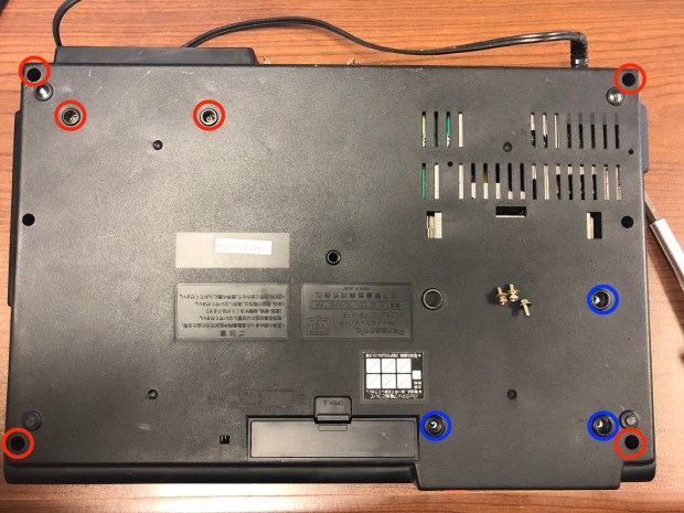
Begin by removing the screws on the corners and the screws holding the rear cartridge slot and the FDD drive. NOTE: the three screws holding the FDD are different than the others and have washers.
Once the screws are removed, flip the unit over and slowly start separating the top cover, beginning with a corner and gradually making your way around. BE VERY CAREFUL when pressing on the release tabs, especially around the FDD, as they can break easily.
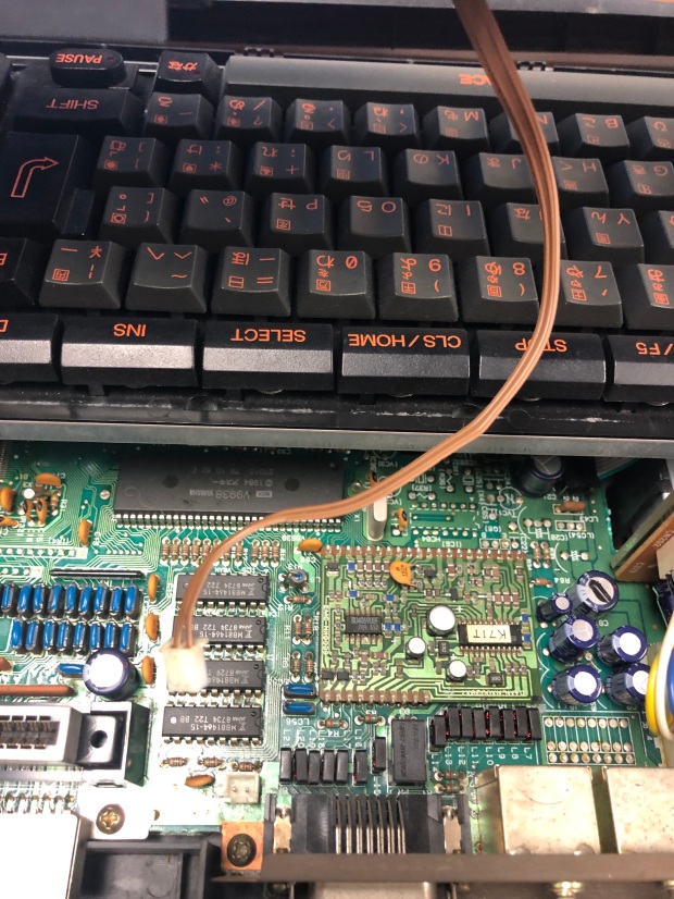
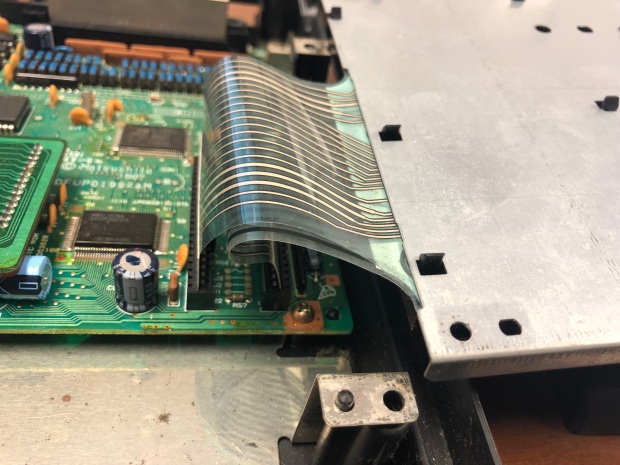
While slowly removing the top cover, unplug the wire connecting the cover to the main board.
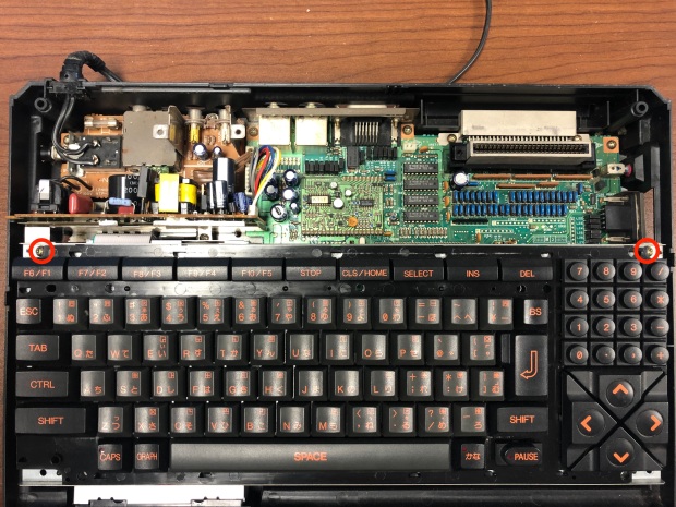
Now that the lid is completely off, locate and remove the two screws holding the keyboard into place.
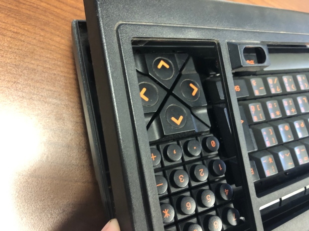
While the keyboard can be completely removed, rotating it over toward the right, while propped on another object, will allow you to keep the ribbon pins connected, as they are fragile.
Part 2: FDD Removal and Disassembly
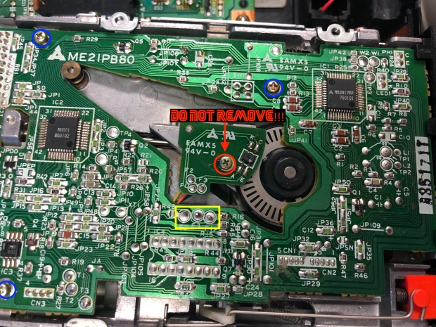
Make sure the three small screws holding the FDD in place from the bottom case (above in blue) have been removed. Next pull the black tabs to the sides to allow the FDD to slide out.
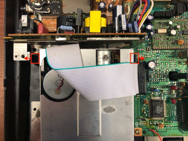
It is possible to keep the ribbon cable connected while continuing with this belt replacement; however, to get clear access to the belt drive and spindle, you’ll need to get under the metal plate on the top of the drive. Begin by flipping the drive over and removing the four screws that hold up to two mounting plates on the sides.
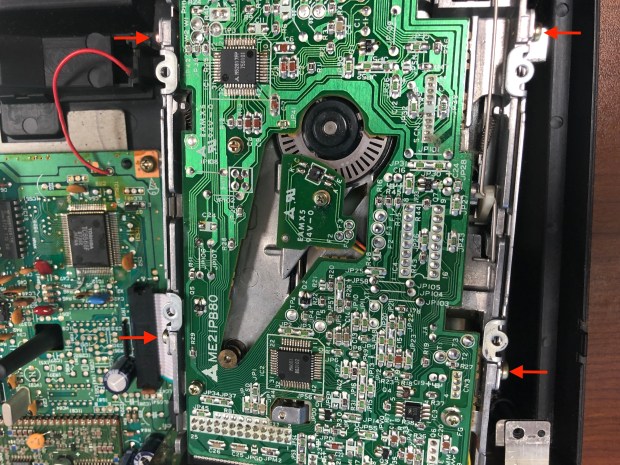
You’ll then be able to start pulling the metal plating off, first by unhooking the tabs from behind the drive’s front cover.
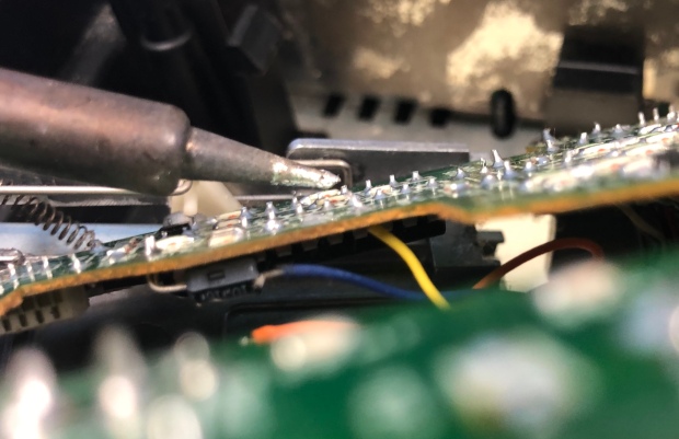
You’ll then need to get under the PCB, so remove the three screws holding it down, but DO NOT remove the screw that’s holding the optical sensor in place. You’ll see the three solder joints that will be undone later to allow the new belt access to the spindle.
With the top metal plating removed, you’ll be able to access and unplug the red and blue wires connected to the PCB.
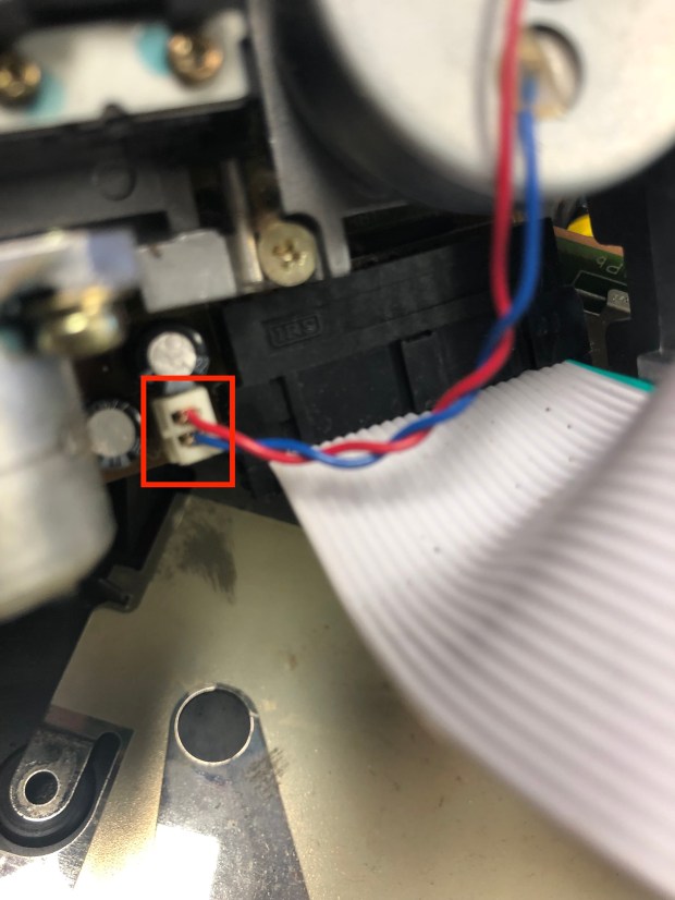
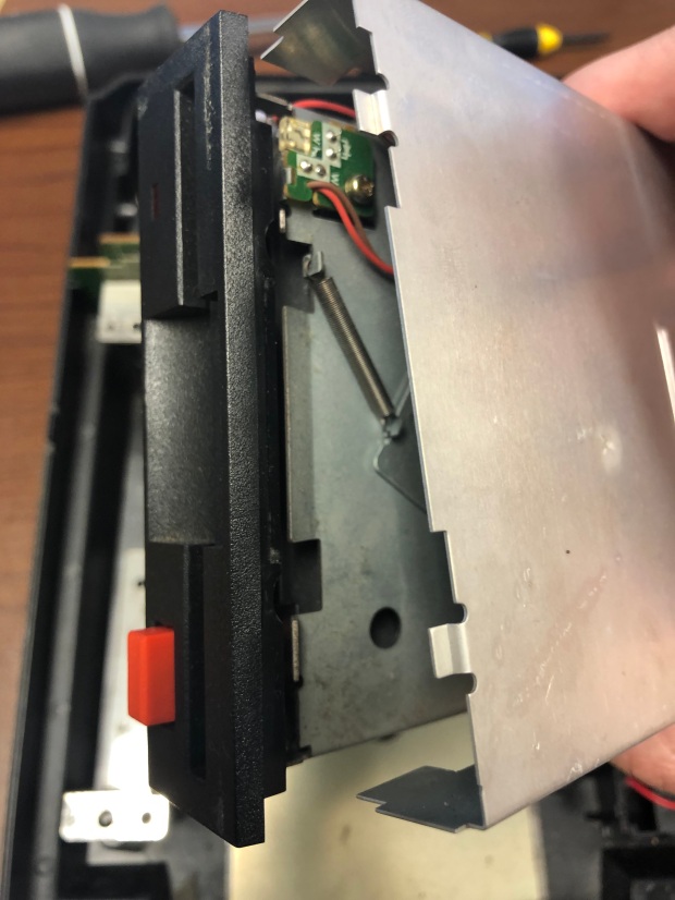
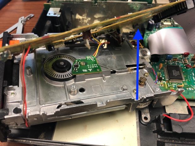
Removing the screws and the red and blue wires will provide enough give that you can lift the PCB board up on one side in order to install the new belt.
Part III: Cleaning and Installation
Chances are the original belt has deteriorated to the point that it has broken off in several places and left a heavy amount of black, sticky residue on the spindle and pulley. You’ll need to do a thorough job removing the broken pieces with anti-static tweezers and cleaning with isopropyl alcohol and cotton swabs. Some stubborn spots may require you to scrape the residue away with a small jeweler’s flathead screwdriver.


I’ll stress here that it is essential that you do a thorough job cleaning the tracks on the spindle and pulley. Make sure to check under the pulley’s top lip for small traces of black goo that are hiding there. The tracks should be slippery clean or the new belt will have problems staying on track. Don’t be surprised if you have to use several cotton swabs to get the job done.


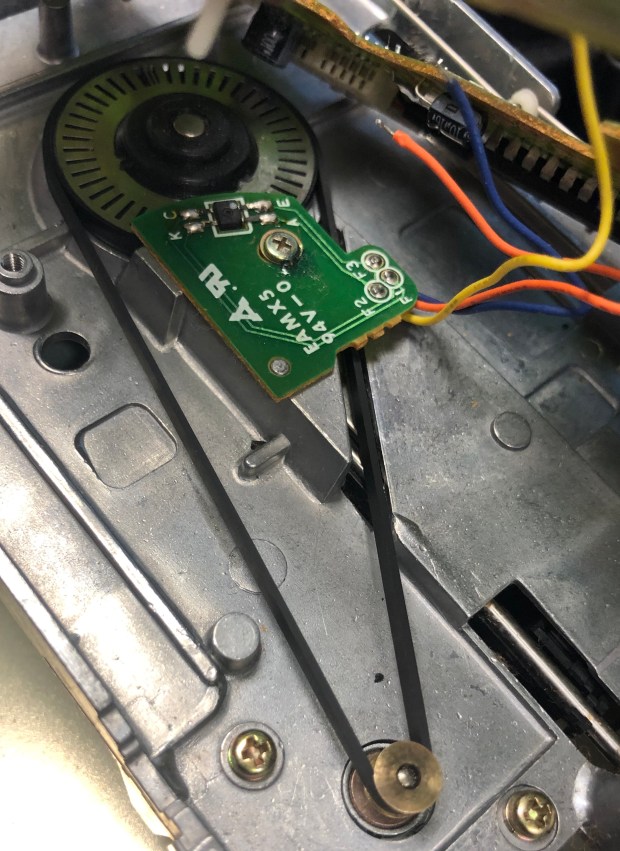
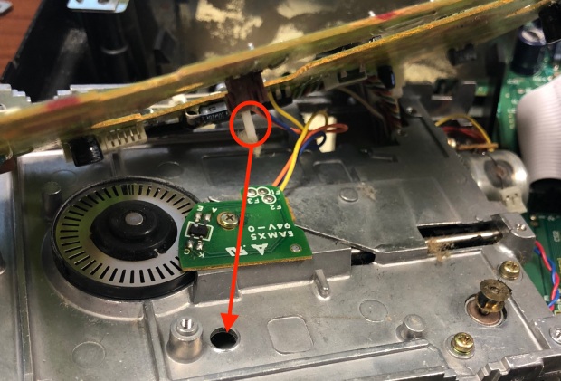
Before installing the new belt, you’ll need to desolder the orange, blue, and yellow wires at pads F1, F2, and F3. The wires run through holes on the PCB, so you can simply warm and melt the solder pad on the top of the PCB and pull the wires out from the bottom of the PCB with the anti-static tweezers. Remember to mark down which color wire goes to which pad.


Then hold the three wires together with your tweezers, so you can circle the belt around the wires from the top. Pull one side of the belt over the optical sensor board and slide the other side of the belt just under the corner of the optical sensor board so you can stretch the belt onto the spindle and pulley.


Use your finger to turn the spindle several complete rotations to ensure that the belt is not getting stuck or riding up on the track. The belt should be tight, but not difficult to turn smoothly.
Part IV: Reassembly
You can then start putting the drive back together, first by soldering the orange, yellow, and blue wires back to F1, F2, and F3 by flowing pads from the top of the PCB and sliding wire through the hole from the bottom with anti-static tweezers. You may need to apply additional fresh solder to the pads on the top of the board after the wires are fed through to ensure joint strength.
With the wires re-soldered, reverse the previous steps by plugging in the red and blue wires and screwing the PCB back in place. Be careful to feed the narrow white pin beneath the PCB through the hole on the tray below before putting the screws back on.
Then, return the metal top plating and side mounting panels and drop the drive back into place between the two black tabs.
Flip the keyboard back over, put the screws back in, and plug the beige wires back in so you can place the unit’s outer shell back on. Finish by screwing in the outer case from the corners and securing the screws back under the FDD and rear cartridge slot.
The entire procedure took me about an hour to complete. Take photos so you can remember how things should look when you put the unit back together; maybe they’ll come in handy if you find a more efficient way that you’d like to share!
If you have any questions or suggestions for a different method, please share in the comments. Thanks for reading!
Sources:
