About 60 Sega Master System games include music data for Frequency Modulation (FM) synthesis. Yamaha’s YM2413 (or OPLL) sound chip, employing only 2 operators, was a cheap alternative to the FM synth chips found in its flagship DX7 keyboards and frequently employed in advanced arcade cabinets. Sega’s Mark III console, released only in Japan, could play the FM data when an external sound unit accessory was connected, and, later, the Japanese version of the Master System included the YM2413 chip in the internal circuitry. Unfortunately, the North American and European releases of the Sega Master System were not built to support the expanded audio, even though most game cartridges retained the FM sound data.
I recently modded two North American Sega Master System consoles to read and perform the FM sound data, using a PCB with the YM2413 chip that was built and designed by Tim Worthington. These mod and kits are explained on this website. Although diagrams and schematics are posted online, I have not found a detailed, step-by-step guide; therefore, I am blogging my experience with installing two kits for those, like me, who may need more guidance. I am not an electrical engineer by any means, so please comment below if you have any suggestions for improvement. My approach worked well for my two consoles, but please be aware that differences exist in the variant releases of the Sega Master System.
EDT’s video proved an invaluable resource to my approach.
SUPPLIES (Required)
-Tim Worthington’s FM Sound Kit (available for purchase here).

-Phillips head screwdriver
-Soldering iron
-Solder and flux
-Drill with 5/16 bit
-Small gauge wire cutters
SUPPLIES (recommended)
-Electrical tape
-Desoldering pump or wick
-Shears/Tin snips
-Jeweler’s flathead screwdriver
-91% Isopropyl Alcohol
-Cotton swabs
PART 1: Preparing the PCB
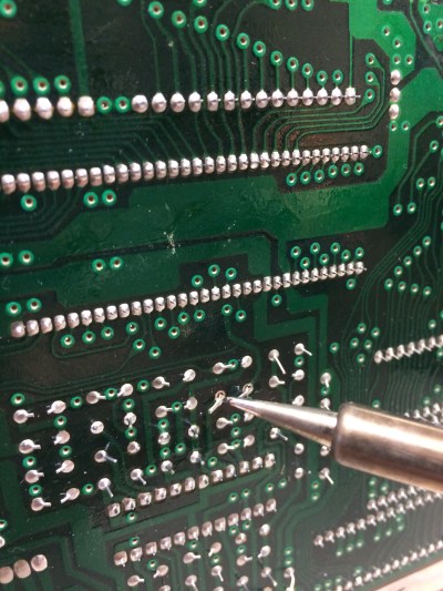
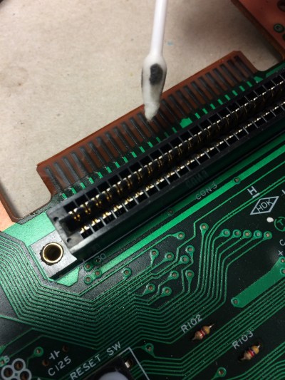
-Slide the pin connector through the holes in the PCB and solder each pin on the rear side. To ensure perpendicular alignment, use something to prop up the board so the two rows of pins are even. Careful not to bridge adjacent pins (see picture); use a desoldering pump or wick to remove any excess solder.

-Slide in the toggle pin connector so that the long end runs parallel to the front of the PCB. Then solder the 3 short end pins on the rear of the board (where the text FM and Japan FM is printed.

-You’ll see that the plug on the provided wire for the toggle switch will slide right onto the 3 pins that are running parallel to the front of the PCB.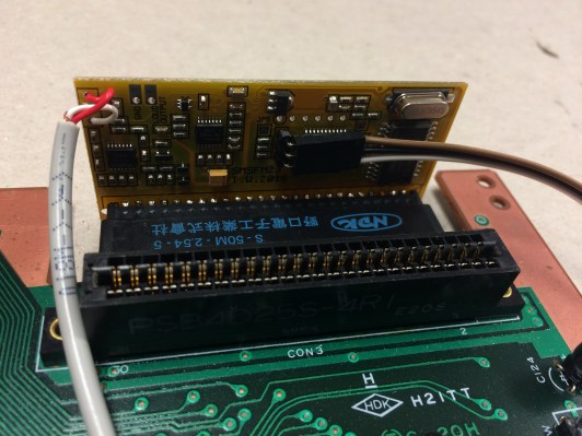
Part 2: Preparing the Toggle Switch
-While the plugs on the wire provided with the kit fit snuggly on the pins for the PCB, I found that they were too small for the terminals on the toggle switch.
-Therefore, I cut off the plug on one end, stripped the 3 wires, and then threaded through and soldered to the 3 terminals, being careful not to bridge any of the three wires with solder on the back of the toggle switch.

-Note: Keep the plug on the other side of the wire, as it will slide easily onto the PCB pins.
Part 3: Preparing the SMS Console
Disassembly. This video may be helpful.
-Remove the six screws on the rear of the console case with the Phillips screwdriver and pull apart. Put screws and console top aside.
-Then remove the 5 screws around the base of the RF shield as well as the screw on top of the RF shield. NOTE: the screw on top of the RF shield is different and includes a washer.
-Finally, remove 7 additional screws that hold the motherboard in place. See the diagram pictured below (one of the two screws on the bottom left is slightly cut out of the photo).

-You can now remove the motherboard.
Wiring SMS motherboard
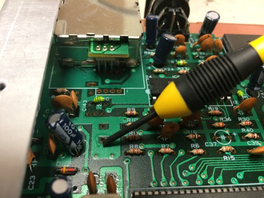
-Remove the electrolytic capacitor at C37 by locating the traces on the rear, warming the existing solder with you iron, and pulling the capacitor away from the other side when the solder is molten.

-Locate ground plane to the left of the same capacitor field and scratch away the green coating with a jeweler’s flathead screwdriver.
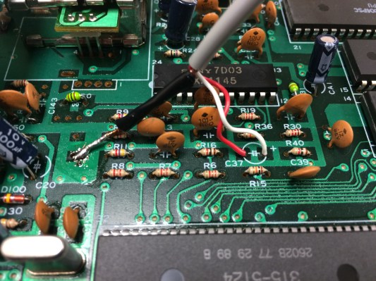
-Prepare the wire provided by stripping the sleeves to reach the target locations on the motherboard and then tin the ends.

-Thread the red and white wires though the positive (+) and negative (-) polarities at C37, and solder the traces on the rear of the motherboard. NOTE: The image provided on the website above has the red and white wire locations reversed. The white wire should be on the right (+ve), and the red wire on the left (-ve).
-Apply flux to the ground plane you just scraped on the component side and solder the threaded copper wire to it. Once completed, wrap electrical tape around exposed wire threads to keep them from reacting to nearby components.
Part 4. Final assembly.
-Clean the pins on the expansion port with some alcohol and cotton swabs.
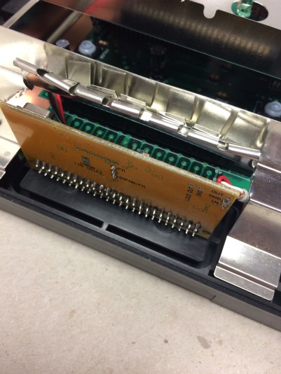
-Slide the pin connector on the PCB onto the expansion port pins. It should slide all the way in tightly.

-Attach the motherboard to the bottom casing with the 7 screws left to the side.
-Use shears or tin snips to cut the RF shield and roll the fingers up so the FM sound board will clear without making contact with the shield.

-Attach the plug on the toggle switch wire to the PCB (if you haven’t already) and put the RF shield back into place with the 5 screws left aside, as well as the smaller one for the top of the shield that has a washer.
-Use a 5/16 bit and drill a small hole through the lid of the console in the desired location. I used the rear left side, so it would have the same clearance as the power and AV cables wherever I set up my SMS.
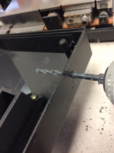
-Make sure the hole is just wide enough to slide the threaded part of the toggle switch through and fasten with the included washer and nut. Electrical tape can be used to hold the wire in place, so it will not block access to the cartridge and card slots.
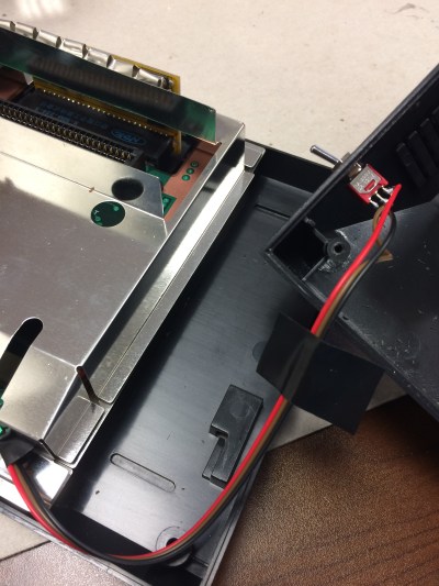
-Carefully place the console lid into position, making sure that the toggle switch wire doesn’t get pinched. (Note: I took photos during both console mods, so pay no attention that the toggle switch wire colors are different at times).
-Put the 6 outer casing screws back in. Done!
Optional. Label the toggle switch. The direction will depend on how the wires were connected to the pins with the plug on the PCB.

Once assembled, you should be able to boot the FM sound data from the Sega Master System cartridges that have it (they are listed at the website above). Some games will require you to use the Japan FM setting on the toggle switch. Other games will require a patch or ROM from a flash cart like the Master Everdrive. You cannot toggle during gameplay, as the FM data is only loaded at boot up.
Many thanks to Tim Worthington for an outstanding mod and kit!!!
Please leave comments below if you have any questions or any suggestions for improvement. I hope this step-by-step guide will be helpful! =)
