Like many others, I modified my original NES with a 47k resistor to support expanded audio playback. While connecting expansion pins 3 and 9 does access the additional channels, the balance is very inconsistent. This is due to variability in the chips added to Famicom cartridges and to the Famicom Disk System and how they were mixed with the primary sound created in the console. Each expansion included both the additional audio data and the instructions for how it should be mixed with a Famicom. A fixed resistor therefore results in a fixed mix with the console.
A potentiometer, used to vary the ratio of voltage divided between two circuits, can be wired as a variable resistor (i.e. rheostat) to provide dynamic control of the extra channels. Instead of connecting all three pins, you just wire one of the outer terminal pins and the middle pin (wiper). I found this image helpful in demonstrating the difference. You could choose to bridge the extra terminal pin to complete the circuit in case the wiper should fail over time.
Since there were no visual guides specifically for a 100k pot mod to the NES, I decided to post my experience. I’m no expert, so I’m grateful for the post by Wesley Almond that guided me along the way. Also, thanks to Brad Smith (a.k.a. rainwarrior) for the 100k pot mod idea.
MATERIALS USED:
A)-regular philips head screwdriver
B)-jeweler’s flathead screwdriver

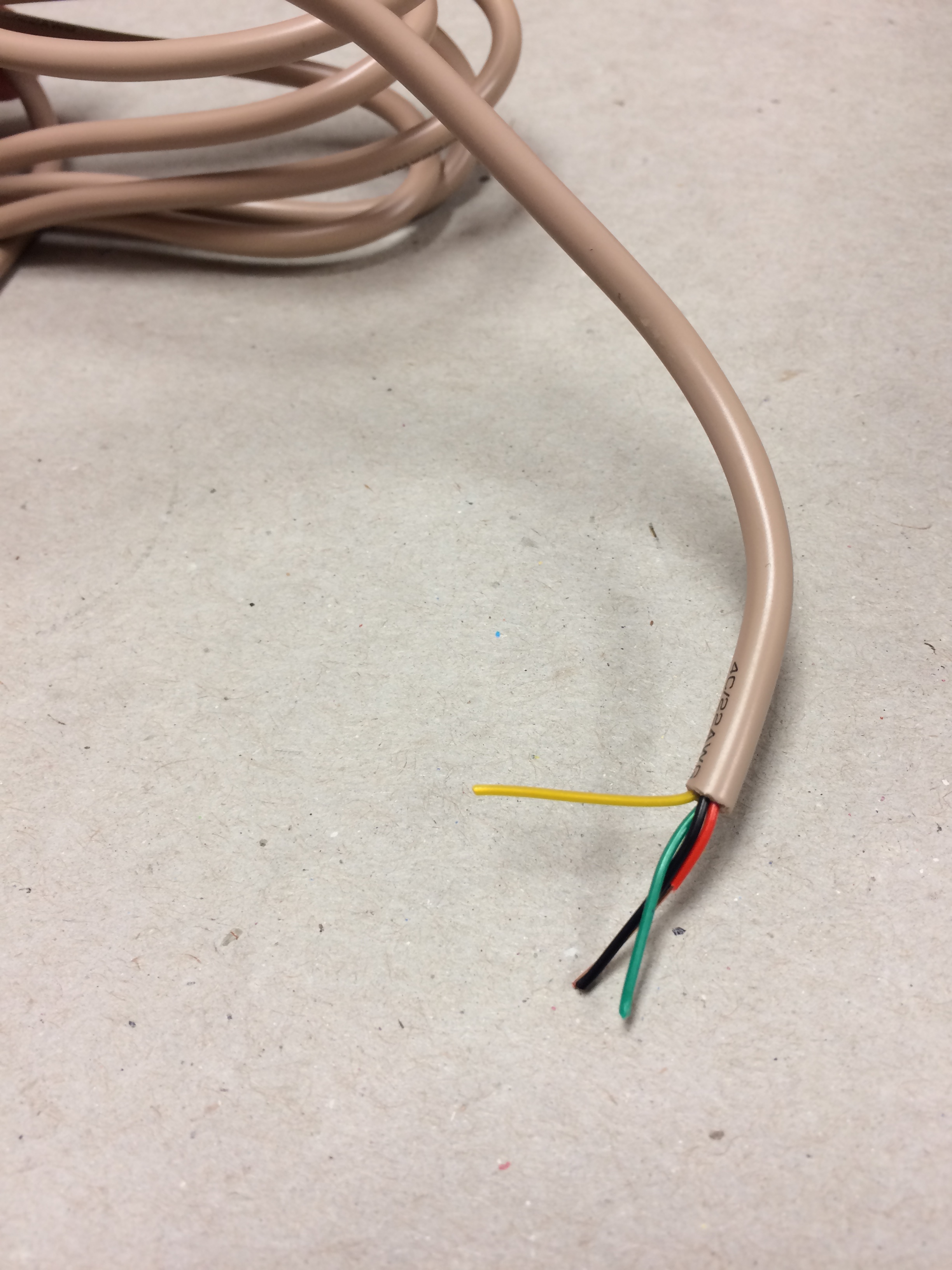
C)-coated, solid wire w/ small gauge. TIP: Have your local electronics shop sell you a few feet of 22 AWG/4 conductor security wire for practically nothing, strip, and choose among FOUR COLORS!
D)-wire stripping pliers (for small gauge)

E)-soldering iron and solder

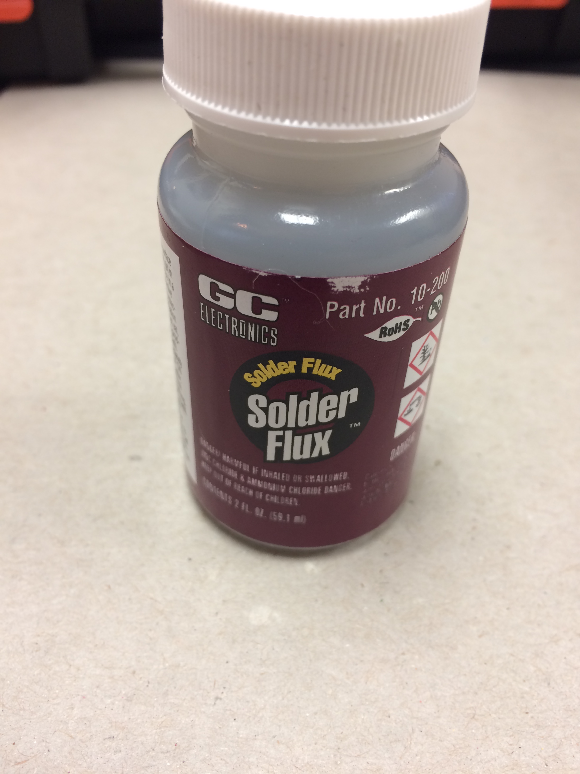
F)-flux: to prevent oxidization at soldering joints
G)-drill with 3/8 bit
H)-100k Potentiometer. TIP: Some come with “off switch” that is engaged with a click when turned all the way, counter-clockwise.

STEPS TAKEN
1-Remove the 6 outer casing screws with the philips head screwdriver.
(NOTE: All of the screws removed in this mod are the same, except for 2 slightly longer ones later in the process. I still recommend keeping them grouped and on a surface where they won’t roll away!)

2. Remove the bottom casing to reveal the heat shield.
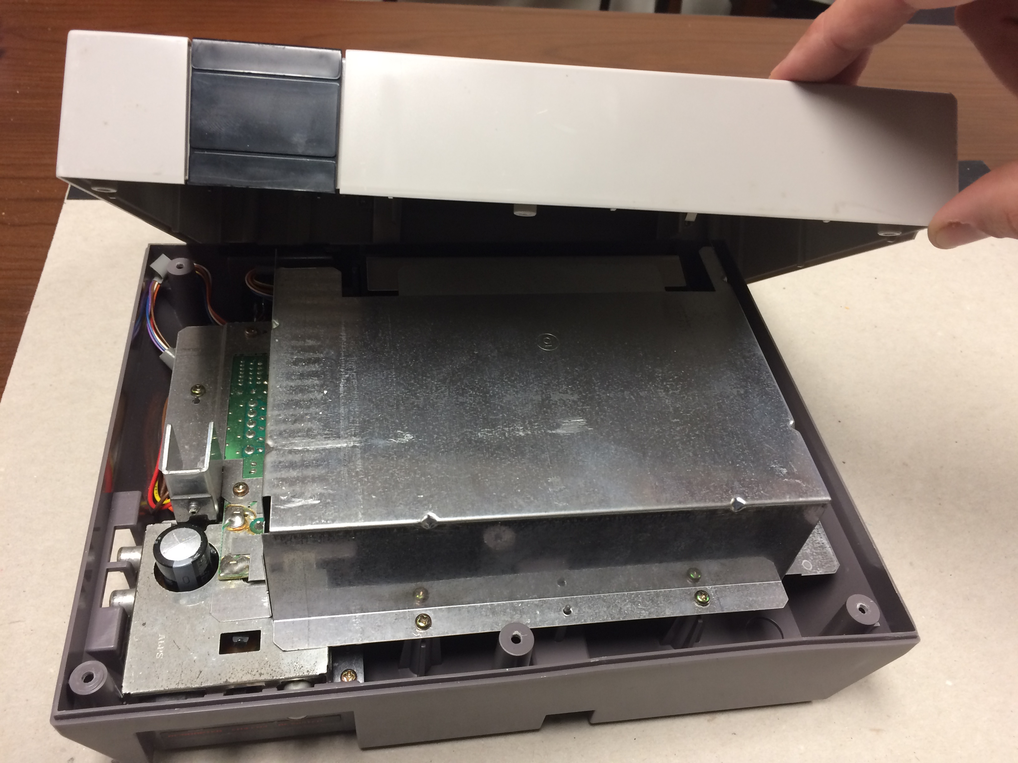
3. Remove the 7 screws on the heat shield + the screws over the RCA and RF jacks.

4. Lift the shield slowly to navigate around any obstacles

5. Remove the 6 screws from the cartridge tray. Note that the inner screws of the bottom pairs (blue) are slightly longer than the other screws.

6. Pull the cartridge tray out and then lift up.

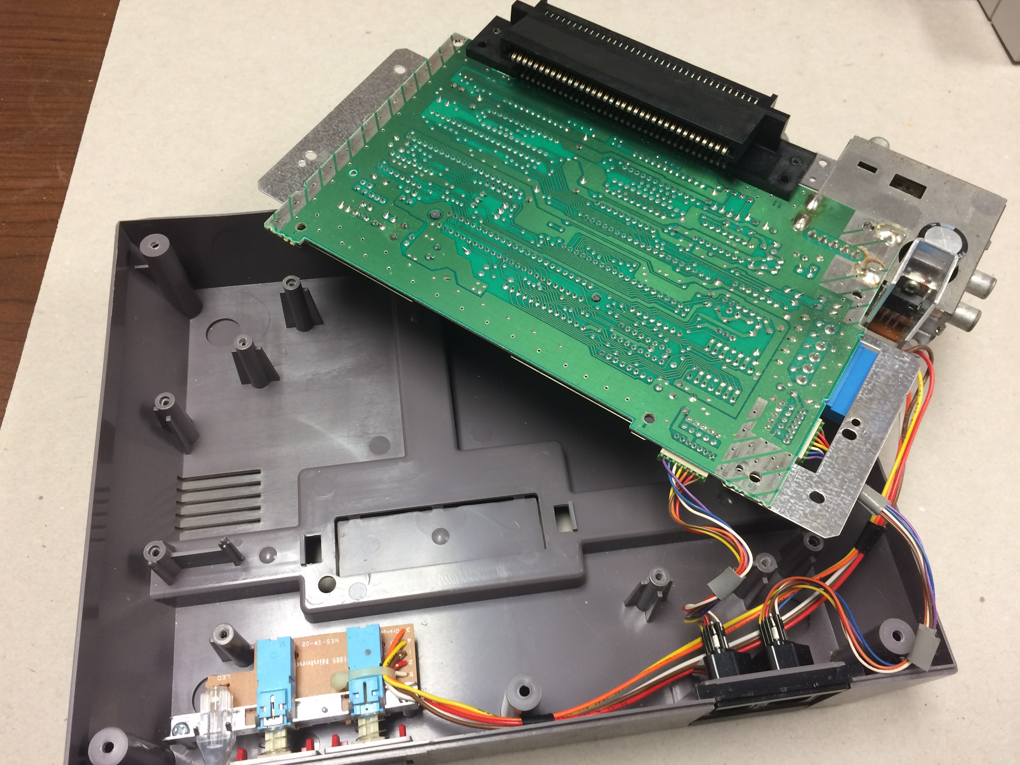
7. Slowly pull the board out and flip over gently around the course of wires.

8. Locate the Nintendo lockout chip and pry off the 4th pin from the left—I used a jeweler’s flathead screwdriver to pop off and bend back.


9. Slowly flip the board back over and set back into the console casing.
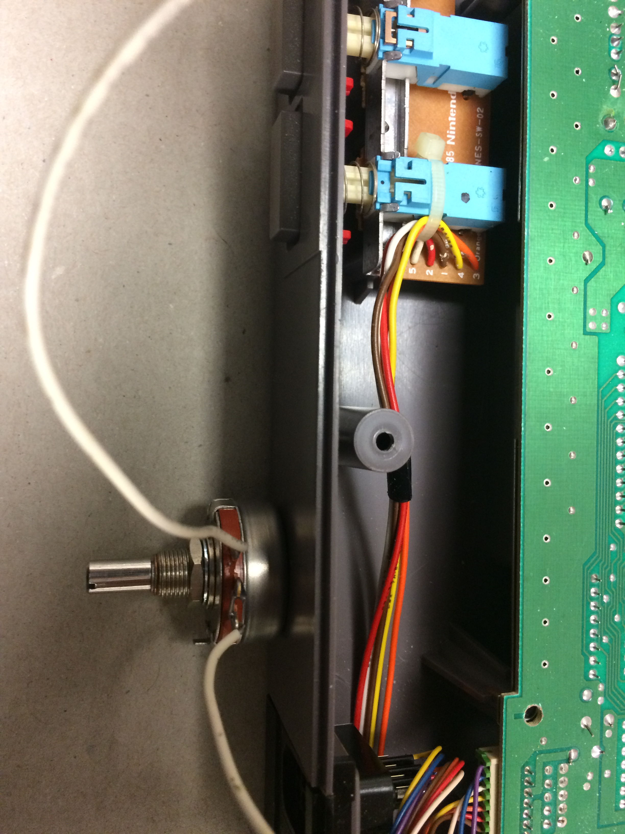
10. Prepare Pot: At this time, warm up and tin your soldering iron. Cut a pair of 5-6 inch wires and strip the coating back on both ends. Warm wires with soldering iron, dip in flux, then warm solder with iron and connect one wire to the middle terminal on the pot, which controls the wiper, and the other to the right terminal on the pot. I shaped my wire like a hook and looped in the pot rings before applying solder.

11. Once the pot has cooled, set it outside the console between the reset button and the controller jacks. Mark your drilling location on the plastic casing where the pot knob will go, leaving enough clearance above the pot to reassemble the console.
12. Drill a small pilot hole and then use a 3/8 drill bit to create an opening for the threaded pot knob. Careful not to drill into the wiring, which can be pulled back slightly and even held out of the way with electrical tape if needed.

13. Apply some side pressure (or use a dremel) to widen the opening as needed until the threaded knob pulls through snug, and then fasten with the nut.

14. Locate pins 3 and 9 on the board, used to channel expanded audio.

15. Solder the wire attached to pot’s middle (wiper) terminal to pin 3 and the wire attached to the pot’s right terminal to pin 9. TIP: Make sure there is enough slack for the wire to run over the board and loop along the bottom of the casing before routing back up to the pot.

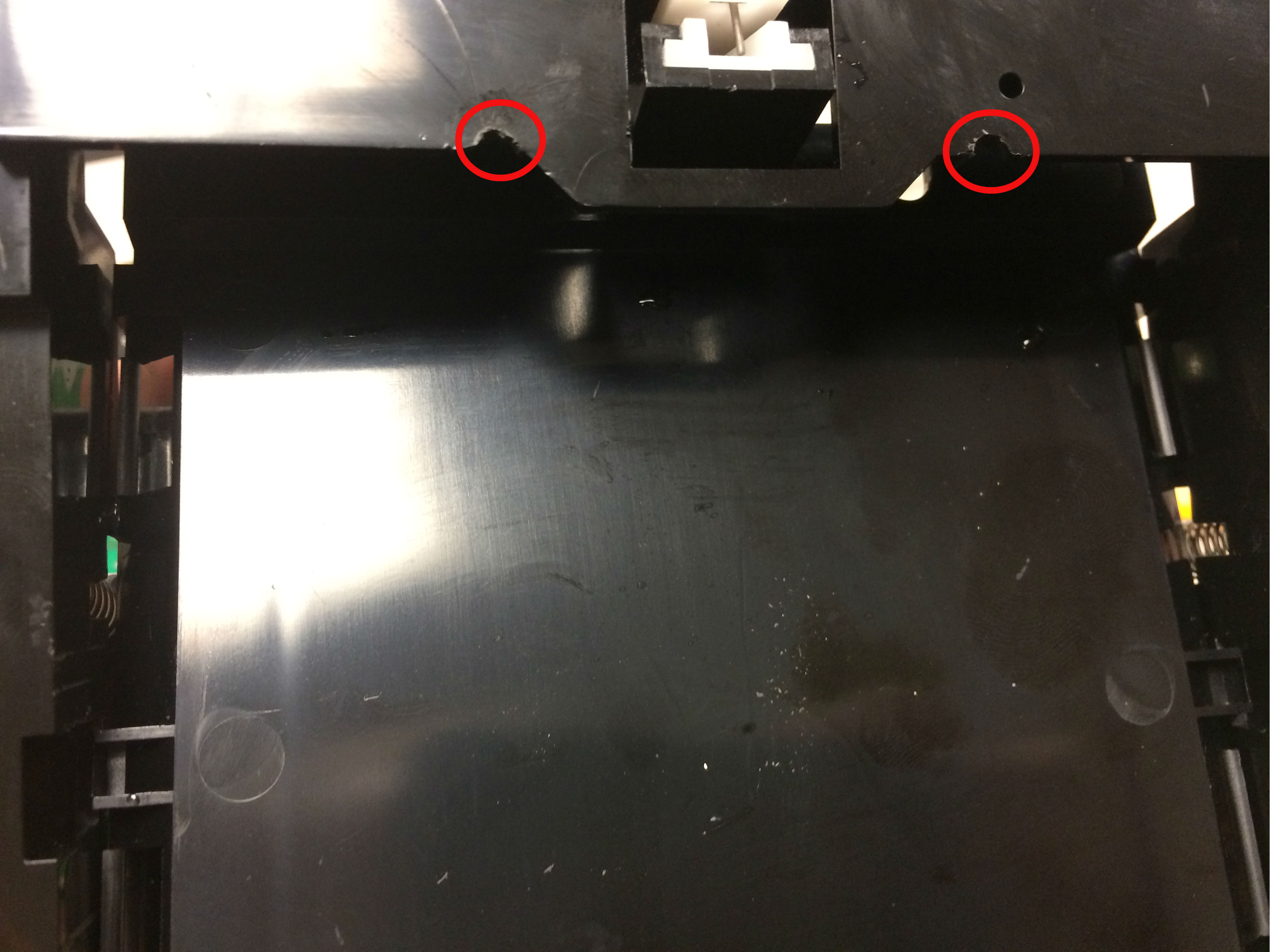
15. Use side of drill bit (or dremel if you have one) to carve out two small openings along the edge of the cartridge tray where the wire will not be pinched when pushing tray down during reassembly. Alternatively, you could use longer wire and run completely around the tray and approach pins from the side.
16. When reassembling the cartridge tray, make sure to slide the wires into the openings before pushing tray down. Also, remember to use the two longer screws in the correct locations.
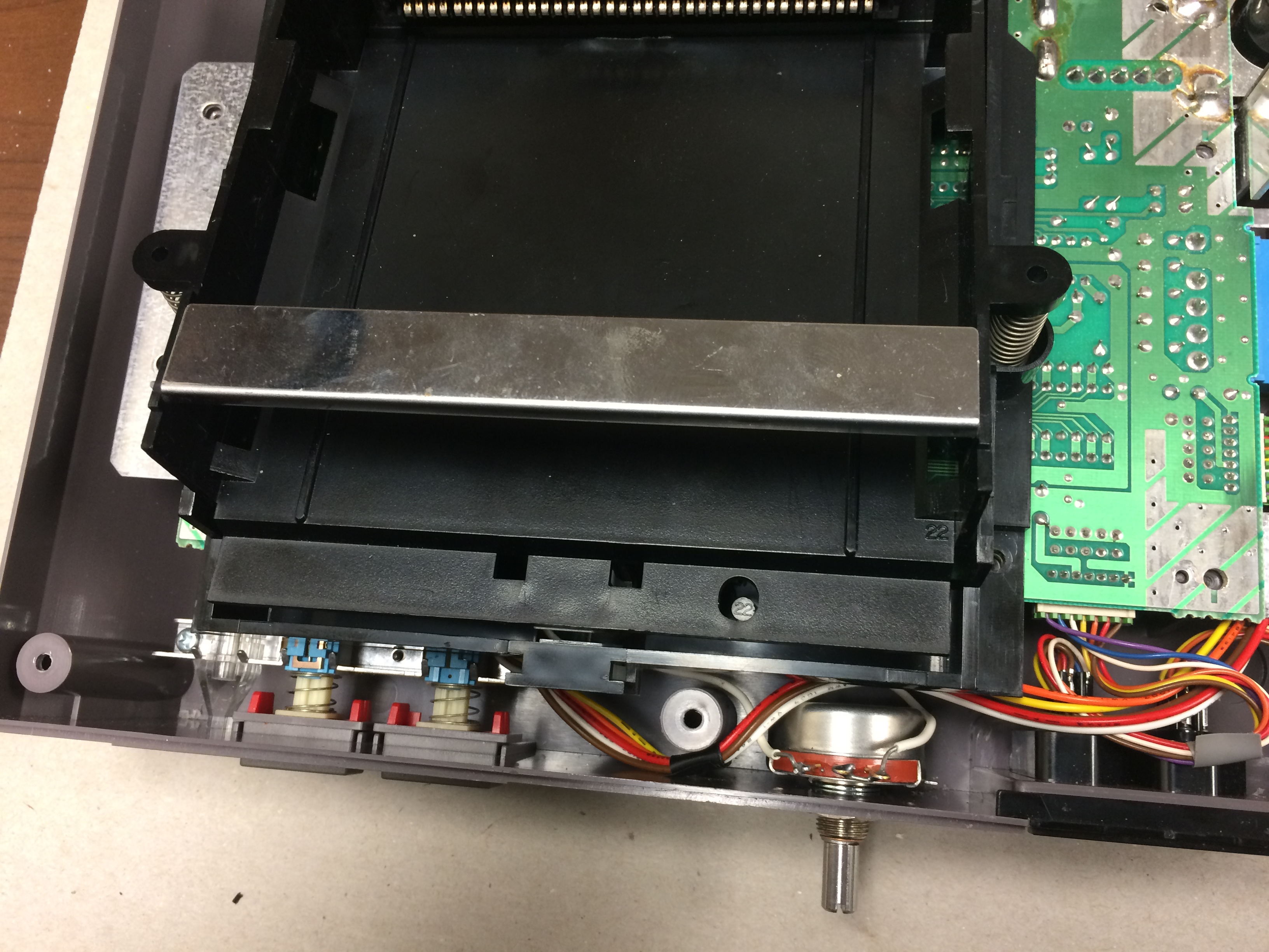
17. Re-attach the heat shield and the bottom casing, and flip over. DONE!

18. Test your modded NES! NOTE: This mod will not work with VRC7 (Lagrange Point) unless you are using an actual Lagrange Point cartridge, with the 60-to-72 pin adaptor wired to route the cartridge’s audio. Most other expanded audio will work via Powerpak flash cart. Use pot knob to mix expanded audio with console audio to your liking! Turn the pot knob off when not in use.
Hope this helps newbies like myself! Please comment with any questions or feedback; if there’s a better way to do this, let me know and I’ll update!

I’ve been meaning to do this for a while, thank you for such a detailed guide! Just one question, can you post a link/part number for the pot you used? I’ve found conflicting info on whether the taper type matters and I’d rather just buy a part known to work properly.
Thanks again!
Thanks for reading the post! I’ve done this mod with two different linear taper potentiometers. Both work well, the only difference being that one has an off switch that is engaged when turning the potentiometer all the way counter-clockwise. The off switch is recommended, as I’ve read reports of some noise interference in some games that do not use the expanded audio, since the connection would remain active when not turned off. Personally, I haven’t encountered any of those games causing the interference with the potentiometer, but there is no reason to risk it. If you find yourself needing to engage the off switch often, I recommend putting a grip on the knob to make it easier to turn all the way. This is the one I’ve used with the off switch and the vendor where I purchased it:
Alpha B100k Potentiometer. Part No. 263822.
http://www.jameco.com/z/31VM501-F3-Taiwan-Alpha-Electronic-Potentiometer-100K-Rv24A01F10-15R1-B100K-Linear-with-Switch-1-2-Watt-335-_263822.html?CID=GOOG&gclid=COnCjK6LsdICFeEV0wodI2QKig
When mixing the expanded audio, the most dynamic change occurs with the VRC6 and the FDS audio. I can confirm this mod works with all expanded audio via the PowerPak flash cart, except for VRC7. VRC7 will not work with this mod unless you are using an actual Lagrange Point cart w/ the 60-to-72 pin adapter wired to route the audio.
Perfect, thank you!
whoa!! i just realized this is from only a few days ago – thanks so much for sharing! i am absolutely going to do this ASAP. btw – you should consider adding a knob of your choice to the front of that pot, to make it a little snazzier 🙂
For sure! A knob with a grip makes turning it off with switch a lot easier!
Great guide! I just ordered an ENIO Exp Board and then started reading more about how 47K fixed isn’t ideal. Since I would prefer not to solder in my actual NES, do you think it would be possible to swap out the 47K resistor on the ENIO board with this 100K potentiometer? That way I’m only modifying the board and not the NES, and I could then route the wires along the crevice on the bottom of the console to the left of the expansion port and fashion a switch to the side (velcro/tape) without drilling anything on the case.
That’s a good idea! I haven’t looked at the ENIO board or its schematics, but if the 47k resistor is performing the same function on the board as the resistor in the mod between pins 3 and 9, then I don’t see why it wouldn’t work. No harm in trying; if it doesn’t work, you can always take the wires off and put the 47k resistor back in. And you will not have made any changes to the NES.
I may have to get a cheap soldering iron and desolder pump, I just hope I don’t fry it, but better that than the NES. My dream front loader would be this 100K pot mod to control expansion audio levels, the stereo/mono mixing mod so that you can control the mixing between speakers, Blinking Light Win, Extended Famicom Converter, Famicom RAM Adapter, FDSStick, and ENIO board. With those you can play the full FDS library with perfect expansion audio, as well as have full control over all the levels with the most possible options. Plus the ENIO board lets you use Famicom peripherals. I don’t even think I’ll go NESRGB, my 2002 KV-20FS100 Sony Trinitron has such a good comb filter that even composite looks amazing.